4
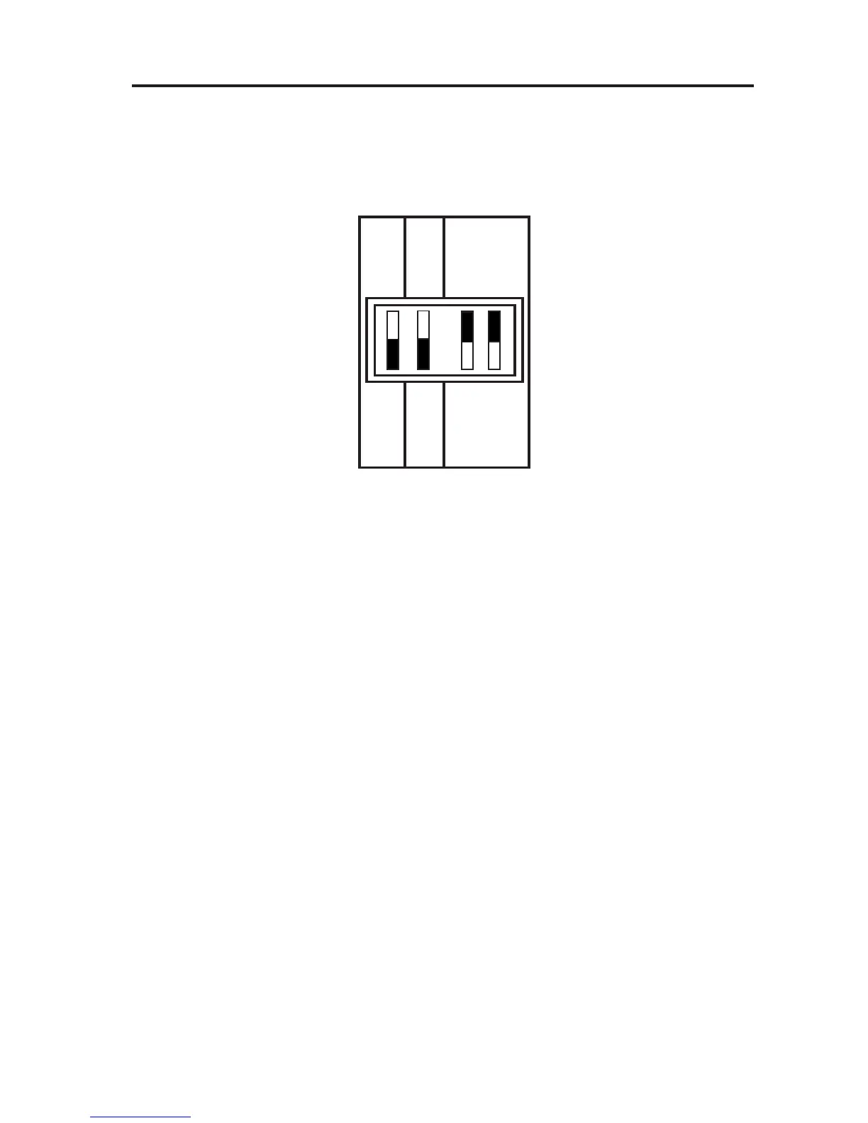
DIL Switch Settings
DIL switch settings
Before mounting the unit, ensure the 4 DIL switches on the rear of
the unit have been moved to the required settings.
MK.9 or SET
The FP975 is supplied fi tted with a Danfoss Randall SET wallplate.
However the FP975 will also mount directly onto a Danfoss Randall
MK.9 wallplate without the need for wiring changes. However
when used with existing MK.9 wallplates the left hand switch
must be set in the MK.9 position to re-confi gure the time control
to match MK.9 wiring connections.
PUMPED or GRAVITY
When this switch is in the PUMPED position the Heating and
Water outputs are UNLINKED. When in the GRAVITY position the
Water output is LINKED to the Heating output so that whenever
the Heating is ON the Water will also be ON regardless of the
Water programme.
Place the switch in the PUMPED position if the system being
controlled is a) fully pumped with a mid-position valve, b) fully
pumped with a two port zone valve in each circuit, c) GRAVITY
Hot Water, PUMPED Heating with a two port zone valve with
SPDT auxillary switch in the gravity primary circuit (and wired in
accordance with diagrams on pages 10-11).
RIGHT
LEFT
TOP
7 DAY
MK.9
5/2 DAY
SET
PUMPED
GRAVITY