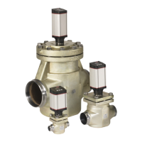
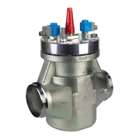
ICM/ICAD Motorized Valve Installation, Programming, and Troubleshooting
Danfoss (USCO / MKS), 11 - 2006 DKRCI.EI.HT0.A1.22 / 520H1639 11
Alarms There are a number of alarms which are excellent indicators of improper installation or
set-up:
Description
ICM
alarm text
Comments
No valve type selected A1 At start-up
A1 and CA will be displayed
Controller fault A2 Internal fault inside electronics
Input error A3
Not applicable if ¡01 = 2 or ¡02 = 2
When ¡03 = 1 and AI > 22 mA
When ¡03 = 2 and AI > 22 mA or AI < 2 mA
When ¡03 = 3 and AI >12 V
When ¡03 = 4 and AI >12 V or AI < 1 V
Low voltage of fail safe supply A4 If 5 V d.c. < Fail safe supply
< 18 V d.c.
Check Supply to ICAD A5 If supply voltage < 18 V d.c.
Problem Possible cause and solution
The valve is not working and an A1 is
ashing in the display.
The ICM valve size was not selected in
parameter ¡26. See the programming
section on page 9.
The valve does not appear to be opening
or closing properly
The ICAD was not mounted properly
on the valve stem. Solution: Check to
make sure that the ICAD was mounted
evenly on the ICM valve
The ICAD is not receiving a proper
input signal. Solution: Use the service
parameters (¡51 for a mA input or ¡52
for a voltage input) to check the input
signal that the ICAD is receiving.
1.
2.
The valve position feedback signal is not
working when using customer supplied
controller/PLC
A power supply was installed in the
4-20mA/0-20mA feedback loop.
The ICAD motor actuator supplies
the power for the 4-20mA/0-20mA
feedback loop. Solution: Remove any
power source that may be supplied to
the feedback loop.
Wiring problem. Solution: Check the
service parameter ¡53 to see what the
ICAD is outputting. If this does not
reveal anything, check the current
output (yellow and blue wires in ICAD
control cable) with an ammeter.
The feedback output signal was turned
o in parameter ¡06. Solution: Check
to make sure the setting in parameter
¡06 is correct.
1.
2.
3.
For all other problems, contact Danfoss.
Troubleshooting Tips