© Danfoss, 2014-03 520L0619 • Rev EB • Mar 2014 5
Safety and Monitoring
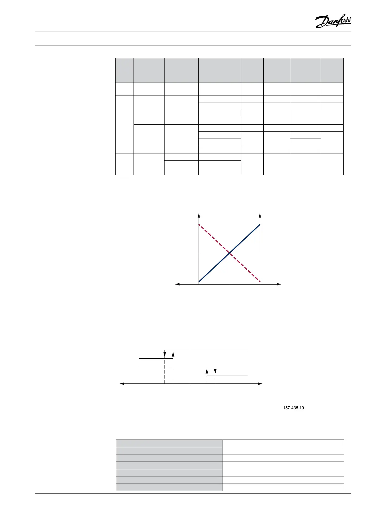
The –SP functionality is a 0,5V to 4,5V inverted feedback with 2,5V as neutral value.
Spool Position Feedback
Spool Position Feedback
(-SP)
Spool travelSpool travel
0.5V
7 mm
100%
B port
7 mm
100%
A port
0 mm
Neutral
2.5V
4.5V
U
sp
Us
Us
Us
Usp
Usp
25% U
DC
50% U
DC
75% U
DC
Fault monitoring overview
Type
Fault
monitoring
Delay before
error out
Error mode
Error
output
status
Fault
output on
PVE
1)
LED light
Memory
(reset
needed)
PVEO
PVEM
No fault
monitoring
- - - - -
-
PVEA
PVEH
PVEP
PVES
PVEU
Active
500 ms
(PVEA: 750 ms)
No fault Low < 2 V Green -
Input signal faults
High ∼U
DC
Flashing red
YesTransducer (LVDT)
Constant red
Close loop fault
Passive
250 ms
(PVEA: 750 ms)
No fault Low < 2 V Green -
Input signal faults
High ~U
DC
Flashing red
NoTransducer (LVDT)
Constant red
Close loop fault
PVE
Float
six pin
Active
500 ms Float not active
High ~U
DC
Constant red
Yes
750 ms Float still active
1) Measured between fault output pin and ground.
Direction Indication
Feedback (-DI)
As shown in the gure, both “DI-A” and “DI-B” signals are “High” when the spool is inneutral
position. When the spool is moving in the A direction, the “DI-A” signal goes “Low” and the “DI-B”
signal stays “High”. The reverse is true when the spool is moved in the B direction.
Direction Indication Feedback (-DI)
DI-A low
DI-B high
DI-A high
DI-B low
Spool position ‘x’
mm [in]
B-port
PVBS away from PVE
A-port
PVBS towards PVE
0.4 0.8-0.8 -0.4 0
Both direction indication signals go low when the error indicator goes high.
Values for both Direction Indicators, pin A and pin B
Transition to low from high 0.8 ± 0.1 mm [0.031 in]
Transition to high from low 0.4 ± 0.1 mm [0.015 in]
Transition to low both pins error pin goes high
Maximum load of “DI-A” , “DI-B” 50 mA
Voltage U
DC
high by load 20 mA > U
DC
–1.5 V
Voltage U
DC
high by load 50 mA > U
DC
–2.0 V
Voltage low < 0.2 V

 Loading...