Do you have a question about the Danfoss PVE Series 4 and is the answer not in the manual?
Details changes made to the document over time.
Lists and defines abbreviations used for PVG and PVE components.
References to other technical documents for PVG products.
Lists relevant international standards and directives applicable to PVE.
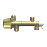
Illustrates and describes different connector types available for PVE.
Provides crucial safety warnings and responsibilities for PVE application.
Introduces the PVE Series 4 as Danfoss's electrical actuator for PVG.
Explains how the PVG valve distributes oil flow to work functions.
Describes the electro-mechanical operation of the PVE actuator.
Details the hydraulic subsystem responsible for spool movement.
Describes the PVEA hydraulic variant, noting its limitations.
Describes the PVHC hydraulic variant and its system requirements.
Explains the mechanical interface, protection, and connectors of the PVE.
Details the PVE's electronic control signal, PWM, and function blocks.
Explains the two fault monitoring versions and triggering events.
Details the monitoring of the control signal voltage (Us) for error states.
Describes the monitoring of LVDT signals for interruptions or short-circuits.
Explains the monitoring of actual spool position against the demanded position.
Details the monitoring of float spool activation within time limits.
Table summarizing fault monitoring features across different PVE types.
Describes the -SP functionality providing feedback on spool position.
Explains the DI feedback signals for spool movement direction.
Details the -NP feature for disabling solenoids based on Us signal.
Emphasizes integrating necessary protection against control valve failure consequences.
Explains FMEA as a tool for analyzing potential risks and failures.
Describes Hazard and Risk Analysis for new applications and safety considerations.
Provides an example of a control system using PVE fault monitoring inputs.
Illustrates a typical wiring block diagram for PVEH with fault monitoring.
Shows fault monitoring for hydraulic deactivation using PVE with DI function.
Notes on PVG 32 usage with fixed displacement pumps and related modules.
Explains how PVE is controlled using low current voltage signals.
Lists PVE variants compatible with PLUS+1 control.
Describes ATEX portfolio PVE monitoring and control characteristics.
Details PVEU control for PLC/microcontroller with 0-10V signal.
Explains how standard PVE variants can be controlled via PWM signal.
Describes the PVEP designed exclusively for PWM control signals.
Explains the PVEO's two independent powered sets of solenoids for activation.
Details two PVE variants supporting float spool functionality.
Describes PVHC current response, hysteresis, and PWM control.
Compares hysteresis across different PVE series (PVES, PVEA, PVEH).
Provides key operating parameters for PVE, including oil consumption and pressure.
Specifies the oil viscosity range and maximum limits for PVE operation.
Defines the operating and storage temperature ranges for PVE.
Lists nominal, minimum, and maximum pilot pressure for PVE and PVHC.
Details enclosure grades and connector types (Hirschmann, AMP, Deutsch).
Provides control specifications for PVHC, including voltage, current, and resistance.
Details the reaction times for PVHC spool movement.
Specifies voltage, current consumption, and reaction times for PVEO/PVEM.
Details control specs including voltage, current, signal, and power for PVE variants.
Provides reaction times for PVEA/PVEH/PVES/PVEU under different conditions.
Details PVEP control parameters like supply voltage, PWM frequency, and impedance.
Shows dimensional drawings for PVE with Hirschmann and AMP connectors.
Provides dimensional drawings for PVE with AMP and Deutsch connectors for PVG 120.
Details PVEO pinouts for DI and standard connections across variants.
Provides pinout data for PVEA/H/M/S/U and PVEU variants.
Details connections for PVE with separate float pin (AMP/Deutsch).
Shows connection pinouts for PVE with DI feature.
Details connection pinouts for PVE with SP feature.
Details connection pinouts for PVE with NP feature.
Specifies PVHC connection requirements and dimensions for AMP/Deutsch.
Shows PVEH connection pinout for float A with 6-pin connector.
Details PVEP connection and control for PWM signals.
Lists PVE code numbers for PVG 32/100 based on connector and feature.
Provides PVE code numbers for PVG 120 application.
Lists connector kits and seals for PVE and PVHC.
Provides cable code numbers for PVED-CC interface and loop cables.
Lists terminator and CAN interface cable code numbers for PVED-CC.
| Category | Controller |
|---|---|
| Protection Class | IP67 |
| PWM Frequency | 100 Hz |
| Communication Interface | CAN bus |
| Operating Temperature | -40 to +70°C (-40 to +158°F) |