PVEP signals (continued)
Duty cycle A-signal
(pin 1)
Duty cycle B-signal
(pin 2)
Function Error Pin output
(pin 3)
10% 0%
0% 10%
≥ 10% ≥ 10% Fault (Error) High
< 10% 10 → 80% B-port flow Low
10 → 80% < 10% A-port flow Low
A > 86% B > 86% Fault (Error) High
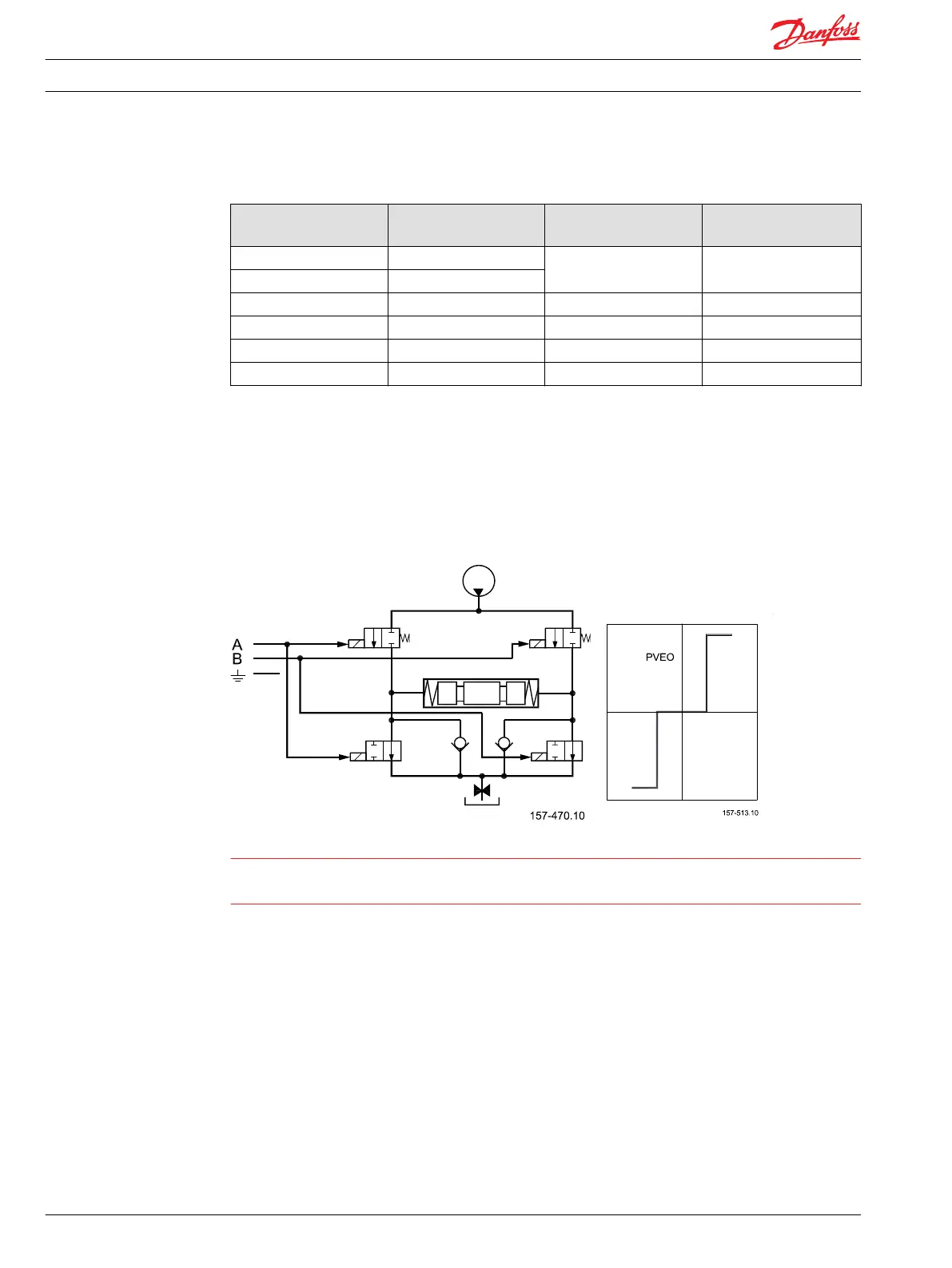
PVEO
PVE ON/OFF activation
The PVEO has two independent powered sets of solenoids. By powering a set of pins the actuator is
activated. By standard mounted PVE the A set gives full flow on A port and B gives on B port. Both
directions activated at same time will keep the spool in neutral.
PVEO schematic and characteristic
Warning
The PVEO is designed to have U
DC
=12 V or U
DC
=24 V.
The solenoids might be activated by voltage down to 6 V.
PVE for float spool
Danfoss has developed two PVE variants to support the float spool. The float spool is a 4/4 spool, where
as the standard is a 4/3 spool giving another characteristic and maximum stroke. These variations are
covered by the built-in electronics. PVE for float spools are not designed for standard 4/3 spools.
There are two variants of float spool PVBS.
•
Float A – 0,8 mm dead band, max flow at 5,5 mm. Float at A = 8 mm, from 6,2 mm partial float.
(PVEH-F with six pin connector gives protection against entering float by using low Us. The float
signal has priority to the Us in the PVEH-F six pin.)
•
Float B – 1,5 mm dead band, max flow at 4,8 mm. Float at B = 8 mm, from 6 mm partial float.
(PVEM-F and PVEH-F with four pin connectors give no built-in protection against entering float.)
Technical Information
PVE, Series 4 for PVG 32/100/120 and PVHC
PVE control
28 520L0553 • Rev GD • Jan 2014

 Loading...