Recommended PWM frequency for PVE (continued)
PVE type PWM frequency
PVEA/H/S/U > 1 kHz
Warning
The PWM is not evaluated by the PVE so variance/failure in period (T) will not be detected.
PVEP
The PVEP is designed for PWM control signals only.
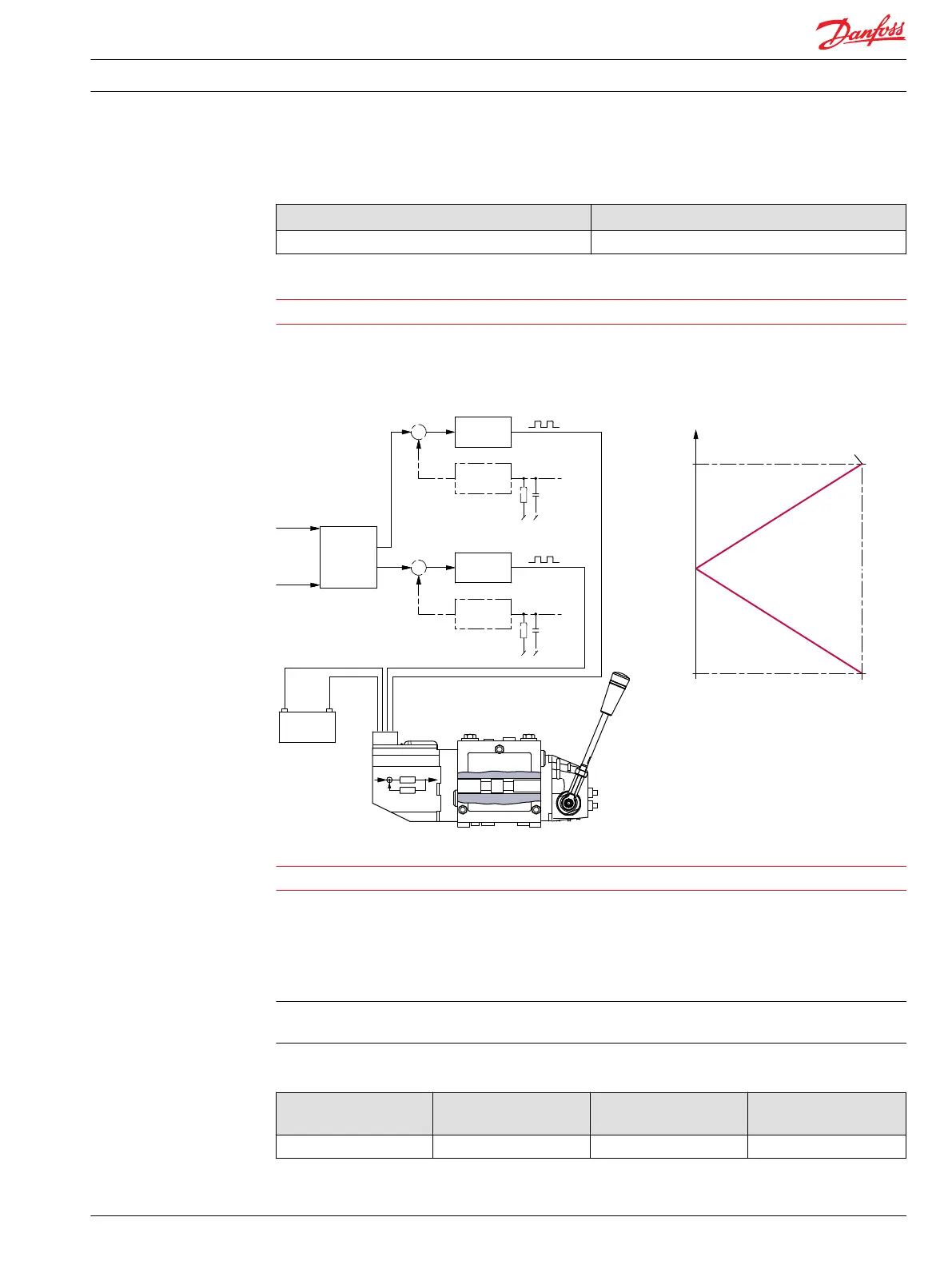
PVEP schematic and characteristic
11 - 32 V
-
+
PVE
Position
to PWM
PWM ratio
Set point
U
s
A
U
s
B
-
B
B
Driver
Sense
Driver
A
A
-7.5
[-0.3]
80%
10%
7.5
[0.3]
-
V310137.B
Spool travel
Sense
Proportional control range
mm [in]
Warning
It is important that the power supply (U
DC
) is connected before the PWM signal.
PWM signals are low power voltage signals; hence no current drivers are needed.
PWM frequency can be chosen between 100 to 1000 Hz.
Current control is not possible with PVEP. The PVEP can also be connected to a control signal like used for
PVHC.
The PVEP performs a true time difference measurement on the PWM input, thus there is no filtering or
conversion involved.
PVEP signals
Duty cycle A-signal
(pin 1)
Duty cycle B-signal
(pin 2)
Function Error Pin output
(pin 3)
0% 0% Neutral Low
Technical Information PVE, Series 4 for PVG 32/100/120 and PVHC
PVE control
520L0553 • Rev GD • Jan 2014 27

 Loading...