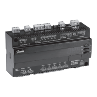
Do you have a question about the Danfoss AK-PC 351 and is the answer not in the manual?
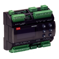
The controller is used for capacity regulation of compressors and condensers in small refrigeration applications.
Energy savings via: Optimisation of suction pressure, Night set back, Floating condensing pressure.
Details available inputs and outputs for the controller, including analogue, digital, and relay types.
Explains daily operation, password protection, and language selection for the controller.
Describes the built-in Modbus data communication and connection to AK-SM 800.
Lists the types of compressor combinations that can be used for regulation in a suction group.
Explains how cut-in capacity is controlled by pressure sensors and set reference, including neutral zone.
Details the control sensor for suction groups, typically a Po pressure transmitter or S4 sensor.
Describes using set or variable references for regulation, including night time increase and limits.
Explains incremental and speed control of fans using relays or analogue output.
Details regulation based on Pc pressure or S7 media temperature sensor, and regulation reference.
Specifies using S7 sensor for media temperature control and high-pressure monitoring.
Covers safety limits for suction pressure, condensing pressure, and discharge gas temperature.
Details functions of LP, HP switches (DI7/DI8) and general alarm input (DI8).
Explains actions and alarms triggered by sensor failures for various sensors.
Illustrates daily user interface displays for one suction group, one condenser group, or a combination.
Describes the initial screen upon delivery and how to access password entry.
Explains the default password and how to set it using arrow keys.
Guides the user through a series of settings to prepare the controller for start-up.
Details the options available in the main menu, including Plant type selection.
Covers starting/stopping regulation, plant type, refrigerant, and unit settings.
Details setting mains frequency and configuring the alarm output relay.
Provides overview of control status, regulation, and pressure zones.
Displays sensor values, reference, running, and requested capacity.
Settings for regulation mode, reference setpoint, neutral zone, and night offset.
Sets regulation reference limits, PI control speed, and first step runtime.
Configures pump down, emergency capacity, and start/off delays for compressors.
Selects the regulating sensor for the suction circuit, e.g., Po or S4.
Configures minimum ON/OFF times, restart, and safety delay for the lead compressor.
Configures minimum ON/OFF times, restart, and safety delay for remaining compressors.
Provides details on compressor 1's Sd gas temperature and operating status.
Reads connected capacity and total operating hours for compressors.
Allows taking a compressor out of operation for regulation purposes.
Displays condenser status, readings, and configures control modes and setpoints.
Adjusts PI regulation parameters like gain factor Kp and integration time Tn.
Selects the regulating sensor for the condenser fan control circuit.
Sets sensor selection, pressure ranges, and reference mode for fan control.
Configures fan modes, control type (PI/P), and status monitoring.
Configures suction pressure safety limits and alarm delays.
Sets limits for condensing pressure, temperature, and S7 sensor with delays.
Configures delayed restart after safety cut-out and sensor alarm reset.
Configures digital inputs for various functions like LP/HP switch, alarm, and text.
Configures display, language, units, screen saver, and logout time.
Sets access codes for three levels: viewing, installer, and configuration.
Configures network settings and performs factory reset.
Details digital output setup for PWM, compressors, fans, and alarms.
Details fixed connection points for digital inputs, including safety and general alarm functions.
Explains analog outputs AO1 and AO2 for compressor and fan speed control.
Lists automatic setup of analog inputs for temperature and pressure sensors.
Shows the current status (on/off) of the digital outputs.
Shows the status of the digital input signals.
Shows the size of the analogue output signals as a percentage of max signal.
Shows pressure and temperature values received by the controller.
Allows manual control of relay outputs, switching between Auto, On, or Off.
Allows manual control of analog outputs, changing signal from 0-100%.
Sets alarm notification importance for general incidents, standby mode, and sensor errors.
Defines alarm priorities for low pressure, high pressure, and compressor safety.
Defines alarm priorities for high pressure and fan safety.
Leads through settings for controller configuration, including IO connections.
Lists general, suction, condenser, and sensor alarms with reasons.
Explains automatic output assignment by the Setup Wizard based on priority.
Details the establishment of digital inputs for safety, switches, and alarm functions.
Describes analog outputs AO1 for compressor speed and AO2 for condenser speed control.
Lists analog inputs for temperature, pressure, and media sensors.
Details digital output and input connections and specifications.
Details analog output and input connections and specifications.
Specifies supply voltage requirements and Modbus communication setup.
Explains how Sd monitoring increases capacity for better cooling of digital scroll compressors.
Details PWM signal control for stream compressors with unloader valves.
Explains closing expansion valves to prevent evaporator overfilling during regulation restarts.
Details supply voltage, frequency, and Modbus communication.
Specifies I/O data, environmental conditions, density, weight, and mounting.
Lists approvals, component references, and load connection notes.
Provides dimensions and notes DIN rail mounting suitability.
Details the product type, function, operation, supply voltage, and code number.
Guide for data communication connection to ADAP-KOOL® Refrigeration control systems.
| Input Voltage | 24 V AC/DC |
|---|---|
| Number of Analog Inputs | 4 |
| Number of Triac Outputs | 2 |
| Communication Protocol | Modbus RTU |
| Enclosure | IP20 |
| Output Voltage | 24 V AC/DC |
| Power Consumption | 5 W |
| Housing Material | Plastic |
| Control Type | PID |
| Storage Temperature | -20°C to +70°C |
| Relative Humidity | 0 to 90% (non-condensing) |
