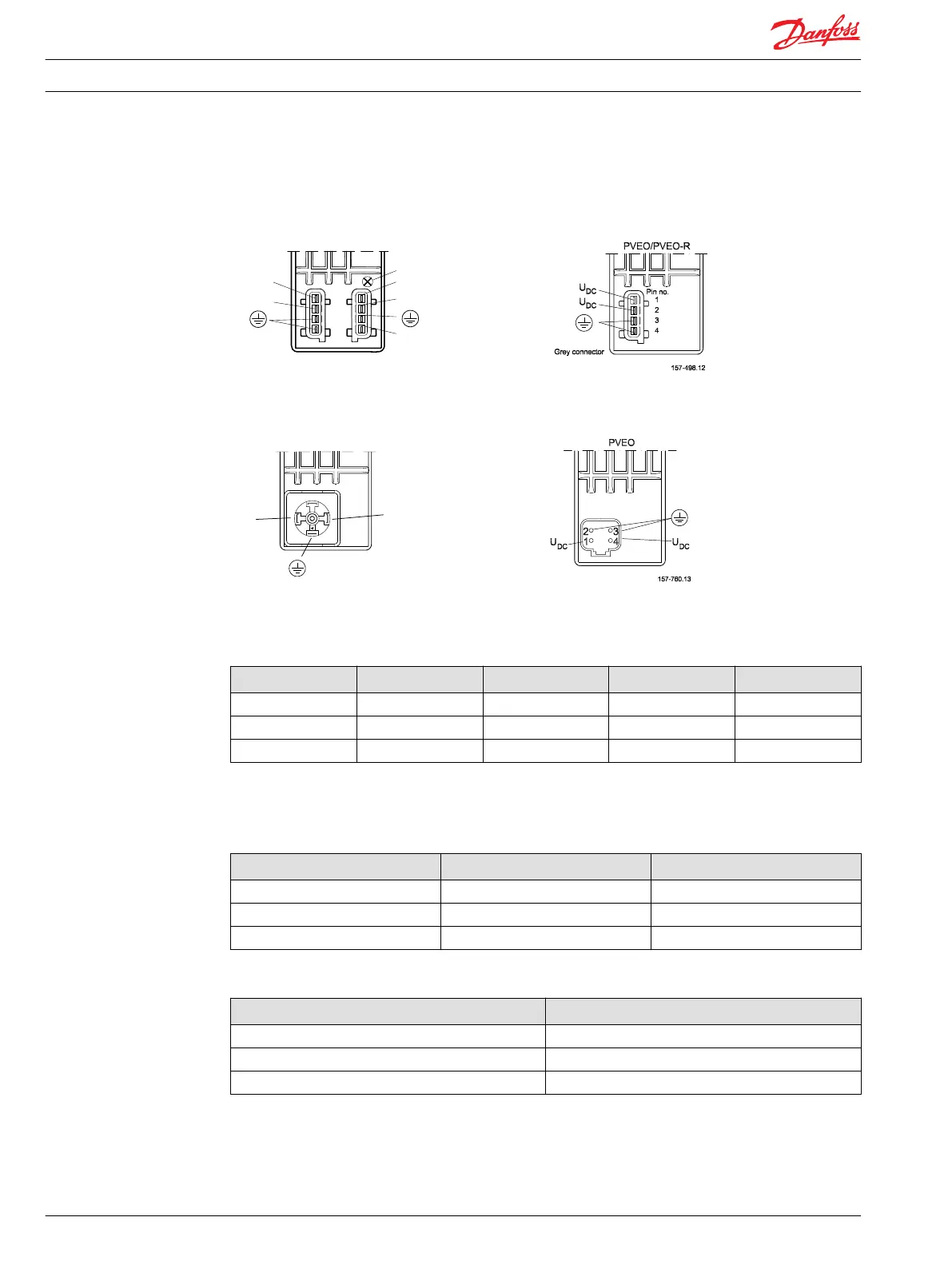
PVEO connection
AMP version of PVEO–DI AMP version of PVEO/PVEO–R
P301 104
Black connector
Grey connector
DI-B
DI-A
PVEO-DI
1
2
4
3
Pin no.
LED
U
DC
U
U
DC2
DC
Hirschmann/DIN version of PVEO / PVEO–R Deutsch version of PVEO
PVEO/PVEO-R
157-502.11
DC
DC
U
U
3
1
2
PVE standard connection data / pinout
PVEA /PVEH / PVEM / PVES / PVEU connection (also with float B, 4–pin)
Connector U
S
U
DC
Gnd Error
AMP pin 1 pin 2 pin 3 pin 4
Hirschmann/DIN pin 2 pin 1 gnd pin 3
Deutsch pin 1 pin 4 pin 3 pin 2
On PVEM the error pin is not used and not connected (pin 3 Hirschmann/DIN). Ground pins are internally
connected.
Control (U
S
) for standard mounted PVEA / PVEH / PVEM / PVES
Function Voltage relative PWM
Neutral 0,5 • U
DC
50%
Q: P → A 0,5 → 0,25 • U
DC
50% → 25%
Q: P → B 0,5 → 0,75 • U
DC
50% → 75%
Control (U
S
) for standard mounted PVEU
Function PVEU
Neutral 5 V
Q: P → A 5 V → 2,5 V
Q: P → B 5 V → 7,5 V
Technical Information PVE, Series 4 for PVG 32/100/120 and PVHC
Technical Data
42 520L0553 • Rev GD • Jan 2014

 Loading...