•
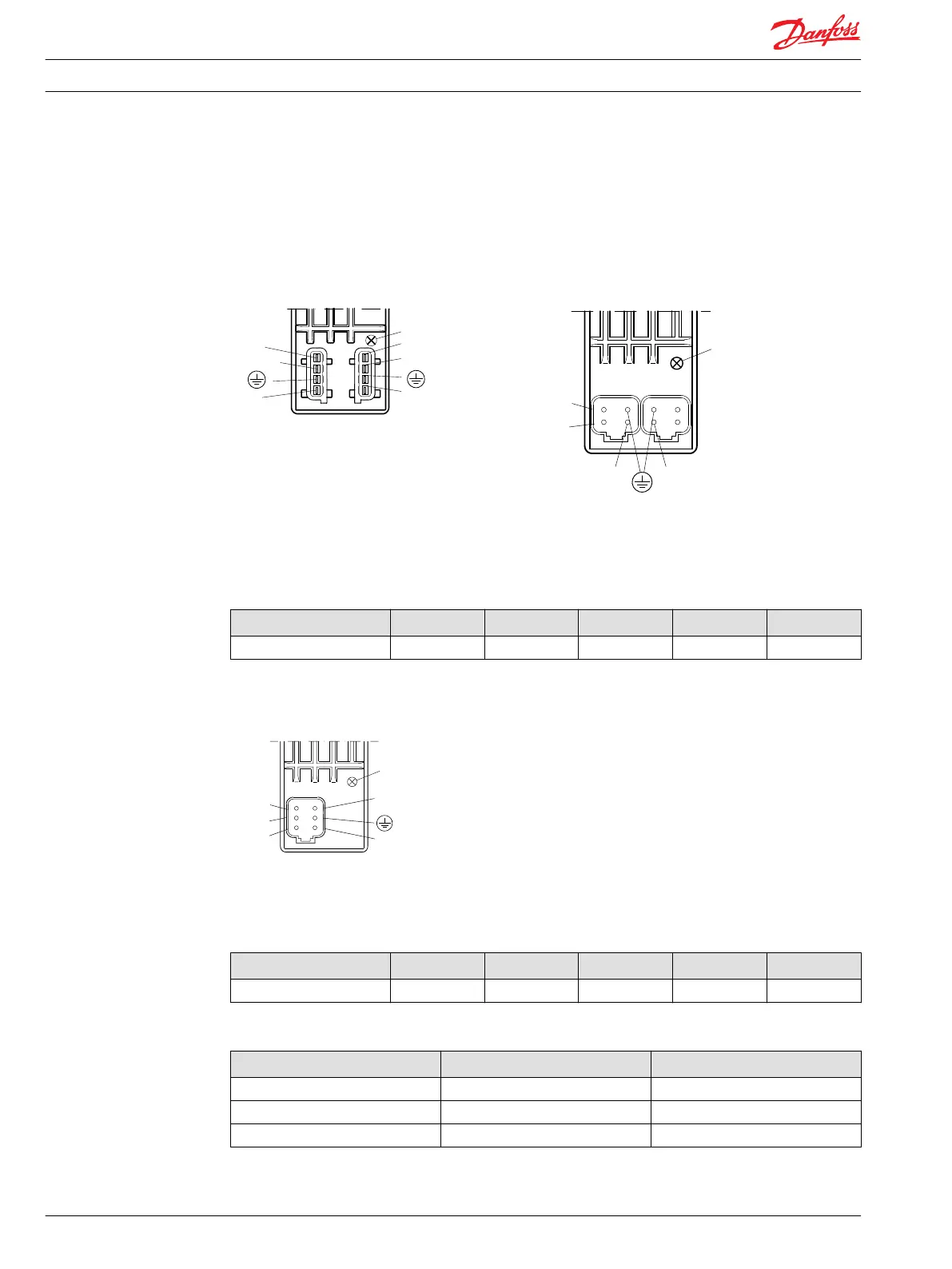
Ground pins are internally connected.
•
U
DC2
only supplies electronics for feedback signal and error pin on PVEA-DI / PVEH-DI. Two separate
power sources can be used.
AMP version: PVEA–DI/PVEH–DI Deutsch version: PVEA–DI/PVEH–DI
Black connector
Grey connector
DI-B
DI-A
PVEA-DI/PVEH-DI
1
2
4
3
Pin no.
LED
U
DC1
S
U
Error
U
DC2
P301 105
2
1
Error
3
4
U
S
U
DC
U
DC2
DI-B
DI-A
2
1
3
4
PVEA-DI/PVEH-DI
LED
Standard PVE with SP
Connection PVE with Spool Position (SP)
Connector U
S
Error SP Gnd U
DC
Deutsch p 1 p 2 p 4 p 5 p 6
Deutsch version: PVES–SP
Not
connected
Error
U
s
3
2
1
4
5
6
Spool position
PVES-SP
U
DC
LED
Standard PVE with NP
Connection PVE with Neutral Power off (NP)
Connector U
S
Error Sfb Gnd UDC
Deutsch p 1 p 2 p 4 p 5 p 6
Control (US) for standard mounted PVEA–DI/ PVEH–DI, PVES-SP, PVEA-NP, PVEH-NP
Function U
S
PWM
Neutral 0,5 • U
DC
50%
Q: P → A 0,5 → 0,25 • UDC 50% → 25%
Q: P → B 0,5 → 0,75 • UDC 50% → 75%
Technical Information PVE, Series 4 for PVG 32/100/120 and PVHC
Technical Data
44 520L0553 • Rev GD • Jan 2014

 Loading...