EasyManua.ls Logo

Danfoss REPI Series - User Manual

Danfoss REPI Series
3 pages
Print Icon
To Next Page IconTo Next Page
Loading...
Page 1 of 3
REPI Series Digital Thermostat Manual
REPI series thermostats are used to control room temperature in industrial, commercial
and residential environment via controlling electric modulating valve with 0-10VDC (4-20mA)
control signal or floating control as well as damper actuator of VAV system.
Electronic control technology is adopted, with green backlit LCD display of: working mode
(cooling “
”, heating “ ”, ventilating “ ”, auto “ ” ); fan speed (low “ ”, med “ ”, high “ ”,
auto “
”); room temperature; setting temperature etc. push button: On/Off “ ”; mode
changeover “ ”; fan speed choose “ ” and temperature adjustment “ ” and “ ”.
Shell: PC + ABS retardant material.
Function :
Detect and Display room temperature
Room temperature setting
Fahrenheit or Celsius degree display
Timing sleep
Control On/Off of cooling and heating equipment
Selectable single speed or three speed fan control
Order Guide:
Output signal
Model
Floating Modulation
Fan
(Single/3-speed)
RS485
Network
Input
Control
Remote
Sensor
REPI-2 Cooling/Heating
REPI-2N Cooling/Heating
REPI-4 Cooling&Heating
REPI-4N Cooling&Heating
Fan: thermostat with fan functions, can be selected with single speed fan or three speed fan by setting parameter.
Remote Control: input signal can be selected by setting parameter.
Specification :
Set temperature range: 0 - 99.5 adjustable
Accuracy displayed:
0.1
Accuracy: ±0.5
Rated Power: < 1 W
Sensor type:
NTC
Display:
LCD
Power:
AC 24V±10, 50Hz/60Hz
Output signal:
AC 24V×2 (0.5A resistive) ,
0 - 10VDC(5mA) / 4 - 20mA (600)
Input signal: dry contact (NO)
Dimensions: 86×86×23mm (W×H×D)
Fixing screw width : 60mm (Standard)
Operations:
" On/Off: Press “ ” buttons to turn on; press “ ” again to turn off.
" Setpoint: With thermostat on, press “
” to reduce the setpoint, press “ ” to increase the setpoint, the setpoint step is
0.5, the setpoint will be confirmed automatically after 5 seconds, and then return to dispay status, press “ ” or “ ” to
check setpoint.
" Mode: With thermostat on, press “
” to change the working mode – Cooling “ Heating ”, Vent " ", Auto “
( Auto is available REPI-4/ REPI-4N).
" Fan Speed: With thermostat on, press “
” to select the desired speed – low speed “ ”, Med speed “ ”, High speed
”, auto “ ”. If single speed fan available, there’s only med speed “ ”.
Under auto speed fan, the fan speed will be changed automatically as below: in low speed when room temperature
is 1 difference with setpoint;in med speed when room temperature is 2 difference with setpoint ; in High speed when
room temperature is 3 difference with setpoint.
" Sleep: Thermostat will get into sleep function after programming.The set Temperature should to be.

Other manuals for Danfoss REPI Series

Question and Answer IconNeed help?

Do you have a question about the Danfoss REPI Series and is the answer not in the manual?

Summary

Thermostat Functions

Room Temperature Detection and Display

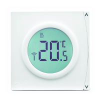
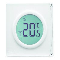
Detects and displays current room temperature.

Room Temperature Setting

Allows the user to set the desired room temperature.

Temperature Unit Display

Option to display temperature in Fahrenheit or Celsius.

Timing Sleep Function

Enables a timed sleep function for the thermostat.

Equipment Control

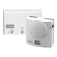
Controls the On/Off operation of cooling and heating equipment.

Fan Speed Control

Selectable single-speed or three-speed fan control.

Thermostat Operations

Power On;Off

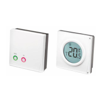
Controls the thermostat's power state using dedicated buttons.

Setpoint Adjustment

Allows increasing or decreasing the target temperature setpoint.

Working Mode Selection

Changes the operating mode (Cooling, Heating, Vent, Auto).

Fan Speed Selection

Enables selection of desired fan speed (low, med, high, auto).

Sleep Function Activation

Initiates the sleep function after programming is complete.

Parameter Configuration

Power On Status Setting

Configures the initial power status (Off, On, Hold).

Fan Speed Mode

Sets fan to single or three-speed operation.

Sensor Selection

Determines whether to use internal or remote sensor.

Temperature Format

Sets the display format to Celsius or Fahrenheit.

Setpoint Limits

Defines minimum and maximum adjustable setpoints.

Dead Band Configuration

Sets the dead band for REPI-4 models.

Sleep Setpoint Configuration

Configures setpoints for heating and cooling sleep modes.

Communication Settings

Configures communication parameters for specific models.

Input Signal Mode

Defines how the thermostat responds to input signals.

Reset Time Settings

Configures reset times for heating and cooling operations.

Output Port Configuration

Sets ports mode, modulation direction, and minimum signal.

Floating Time Configuration

Sets minimum and maximum times for floating control.

PID Control Settings

Enables/disables and sets override values for PID control.

Display Output Settings

Configures output value display based on PID control status.

Input Signal Management

Manages input signal validity and override conditions.

Display Mode

Selects whether to display room temperature or set-point.

External Sensor Configuration

Defines parameters for configuring external sensors.

Low Temperature Protection

Sets start and stop temperatures for low temp protection.

Switch Settings

PCB Switch Configuration

Details the function of each of the 5 poles switches on the PCB.

Mounting and Wiring

Installation Mounting Procedure

Step-by-step guide for mounting the thermostat unit.

Wiring Diagram and Notes

Illustrates wiring connections and provides important notes.

Overview

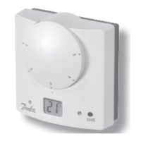
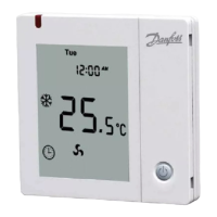
The Danfoss REPI Series Digital Thermostat is designed for controlling room temperature in industrial, commercial, and residential environments. It achieves this by managing electric modulating valves with 0-10VDC (4-20mA) control signals or floating control, as well as damper actuators in VAV systems.

Function Description:

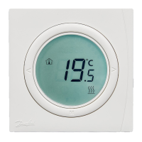
The thermostat utilizes electronic control technology and features a green backlit LCD display. This display shows various information including the current working mode (cooling, heating, ventilating, auto), fan speed (low, medium, high, auto), room temperature, and setting temperature. Users interact with the device via push buttons for On/Off, mode changeover, fan speed selection, and temperature adjustment. The device's shell is made from PC + ABS retardant material, ensuring durability and safety.

Key functions include:

  • Temperature Detection and Display: Accurately detects and displays the current room temperature.
  • Temperature Setting: Allows users to set their desired room temperature.
  • Temperature Unit Selection: Supports display in both Fahrenheit and Celsius degrees.
  • Timing Sleep: Features a timing sleep function for energy saving and comfort.
  • Equipment Control: Controls the On/Off status of cooling and heating equipment.
  • Fan Control: Offers selectable single-speed or three-speed fan control.

Important Technical Specifications:

  • Set Temperature Range: Adjustable from 0 to 99.5°C.
  • Displayed Accuracy: 0.1°C.
  • Accuracy: ±0.5°C.
  • Power Supply: AC 24V ±10%, 50Hz/60Hz.
  • Rated Power: Less than 1 W.
  • Output Signal: AC 24V × 2 (0.5A resistive), 0-10VDC (5mA) / 4-20mA (600Ω).
  • Input Signal: Dry contact (NO).
  • Sensor Type: NTC.
  • Display Type: LCD.
  • Dimensions: 86 × 86 × 23mm (W × H × D).
  • Fixing Screw Width: 60mm (Standard).
  • Output Signal Models:
    • REPI-2: Floating, Cooling/Heating, Fan (Single/3-speed), RS485 Network, Input Control, Remote Sensor.
    • REPI-2N: Floating, Cooling/Heating, Fan (Single/3-speed), RS485 Network, Input Control, Remote Sensor.
    • REPI-4: Floating, Cooling & Heating, Fan (Single/3-speed), RS485 Network, Input Control, Remote Sensor.
    • REPI-4N: Floating, Cooling & Heating, Fan (Single/3-speed), RS485 Network, Input Control, Remote Sensor.
    • Note: Fan functions can be selected between single-speed or three-speed via parameter settings. Remote control input signal can also be selected via parameter settings.

Usage Features:

  • On/Off Control: Press the "Power" button to turn on and press it again to turn off.
  • Setpoint Adjustment: With the thermostat on, use the "Down" button to reduce the setpoint and the "Up" button to increase it. The setpoint step is 0.5°C. The setpoint is automatically confirmed after 5 seconds, returning to display status. Users can press "Down" or "Up" to check the setpoint.
  • Mode Changeover: With the thermostat on, press the "M" button to cycle through working modes: Cooling, Heating, Ventilating, and Auto (Auto mode is available for REPI-4/REPI-4N).
  • Fan Speed Selection: With the thermostat on, press the "Fan" button to select the desired speed: low speed, medium speed, high speed, or auto. If only a single-speed fan is available, only medium speed will be selectable.
    • In auto speed fan mode, the fan speed adjusts automatically based on the room temperature difference from the setpoint:
      • Low speed: 1°C difference.
      • Medium speed: 2°C difference.
      • High speed: 3°C difference.
  • Sleep Function: The thermostat enters sleep mode after programming, and the set temperature adjusts accordingly.
  • Setting Sleep Time: Press the "M" button for 3 seconds until the "Sleep" icon displays. A countdown number appears in the center of the LCD. Use "Up" or "Down" to adjust the desired sleep time (maximum 48 hours). The thermostat returns to working status after 5 seconds, with the "Sleep" icon flashing to indicate counting down. The setpoint will be replaced by the sleep setpoint.
  • Exiting Sleep Function: When the thermostat is in sleep mode, the "Sleep" icon flashes. Press "Power" or "M" to exit.
  • Keypad Lock: Press "Up" and "Down" simultaneously for 10 seconds until the "Lock" icon displays to activate. In this state, all keypad functions are locked. To unlock, press "Up" and "Down" simultaneously for 10 seconds until the "Lock" icon disappears.
  • Parameter Settings: With the thermostat off, press the "M" button for 10 seconds to enter the menu to set parameters. The device offers a wide range of configurable parameters, including:
    • Power on status (Off, On, Hold).
    • Fan speed type (Single Speed, Three Speed).
    • Fan mode (DA, DB).
    • Sensor selection (Internal, Remote).
    • Temperature format (Celsius, Fahrenheit).
    • Temperature calibration (-20.0 to +20.0).
    • Minimum and maximum setpoints (0-99.5°C/F).
    • Dead band (REPI-4 only, 0-10).
    • Heating & Auto sleep setpoint (0-99.5°C/F).
    • Cooling sleep setpoint (0-99.5°C/F).
    • Comms# (REPI-2N; REPI-4N, 1-32).
    • Input Signal Mode (Invalid, Changeover (REPI-2), sleep without input signal, Off without input signal).
    • Heating and cooling reset times (10-300 sec).
    • Ports mode (Modulation & Floating, On/Off).
    • Valve status at turn off (Close, Hold, Open).
    • Modulation direction (10V Open, 10V Close).
    • Modulation minimum signal (0-128Bit).
    • Modulation proportional (1-20).
    • Floating minimum and maximum times (1-9 sec, 10-300 sec).
    • Disable/Enable bypass PID control.
    • Override and display output values when bypass PID control is enabled (0-255).
    • Input signal management (Input valid, Override Input: open, Override Input: close).
    • Display room temperature or set-point.
    • Configuration external sensor (B values: 3950, 3450, 3900, User define via network).
    • Start and stop temperatures for low temperature protection.
    • Settings are confirmed 20 seconds after adjustment and the device returns to the Off state.

Maintenance Features:

  • Installation:
    1. Open the back panel with a screwdriver.
    2. Connect the wires according to the provided wiring diagram.
    3. Fix the base with screws.
    4. Fix the front panel and complete the installation.
  • Wiring Diagrams: Separate wiring diagrams are provided for REPI-2/2N and REPI-4/4N models, detailing connections for modulating control (cooling/heating), fan (HI, MED, LOW), input, RS485, and remote sensor.
  • Switch Settings: A 5-pole switch on the PCB allows configuration of various settings:
    • Location 1: ON for 120 ohm Resistance between AB wires; OFF for No Resistance.
    • Location 2: ON for Port 1 Modulation 0-20mA; OFF for Off.
    • Location 3: ON for Port 1 Modulation 0-10VDC; OFF for Off.
    • Location 4: ON for Port 2 Modulation 0-20mA; OFF for Off.
    • Location 5: ON for Port 3 Modulation 0-10VDC; OFF for Off.
  • General Maintenance Note: It is crucial to connect all wires strictly according to the wiring diagrams and keep them away from water, mud, and other materials to prevent damage to the unit.

Danfoss REPI Series Specifications

General IconGeneral
BrandDanfoss
ModelREPI Series
CategoryThermostat
LanguageEnglish

Related product manuals