2
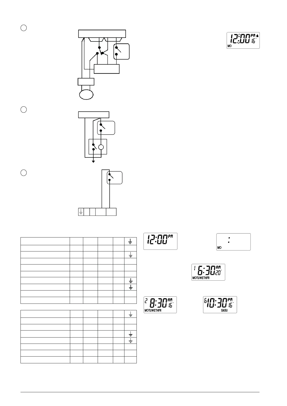
Fig.3. RUN mode
N L
CYL.
STAT
1
3
TP
3 PORT VALVE
BOILER
PUMP
TIME CONTROL
DHW HTG
ON OFF ON
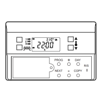
ROOM STAT
REPLACEMENT
IN HEATSHARE
SYSTEM
1
(
D) Drayton
(H) Honeywell
(L) Landis & Gyr
(P) Potterton
(R) Randall
(S) Satchwell/Sunvic
(SO) Sopac
(SW) Switchmaster
WIRING CONVERSIONS (see key to manufacturer below)
1
TP
3
BOILER TERMINALS
3
COMBI BOILER
CONTROL
N L OUT IN
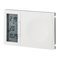
2
ZONE CONTROL
MAINS
NEUTRAL LIVE
1
3
TP
ZONE
VALVE
CONTROL CIRCUIT
TYPICAL CIRCUIT DIAGRAMS
USER INSTRUCTIONS
INITIAL START-UP
Slide the battery cover to the left to reveal
the programming buttons. Slide the cover
further left to reveal the batteries. Remove
the paper insulator from between the
batteries and contacts. Reset the unit as
described below. The blank display changes
to that shown in Fig.3. (if the actual air
temperature in proximity of the unit is higher than 16°C the flame
symbol will not be displayed. The day will only appear on models
TP3 and TP5.) Slide the battery cover to the right but leave the
buttons visible
.
RESET
The unit may be reset to 12:00PM (MO) and the factory set
programme by pressing and holding down the four buttons,
temperature s and t, time + and -, until the display goes blank.
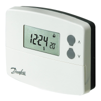
SETTING THE CLOCK
Press the PROGRAMME button once; the colon is no longer
flashing, (see Fig.4.). Use the + and - button to set the time. Hold
down a button to change the time quickly; press and release a
button to change the time by one minute. When the time and AM
or PM are correct, press the PROGRAMME button to start the
clock. On models TP2 and TP4 "Set Day" (Fig.5.) does not occur.
If you have a TP3 or TP5, now only the day and the colon are on
display, (Fig.5.). Use the + or - button to select the correct day.
Press PROGRAMME to display the first setting (Fig.6.).
REVIEWING THE EXISTING SETTINGS AND
PROGRAMMING YOUR OWN
Now each press of the PROGRAMME button shows, in, turn, the
set times, (six with the TP2 and TP4, twelve with the TP3 and TP5),
together with their associated control temperatures. Figs. 6 to 8
show the display of various settings in the sequence. The time and/
or temperature of each setting may be altered to your own
requirements using the + and - (time) and s and t (temperature)
buttons.
Fig.5. Set day. TP3 & TP5 only.
Fig.8. Last setting.
RUN
➟➟
➟➟
➟
Fig.7. Setting 2.
➟➟➟➟➟➟
➟➟➟➟➟➟
➟➟➟
Fig.4. Set time
➟➟
➟➟
➟
Fig.6. Setting 1.
➟➟➟➟
➟➟➟➟
➟➟
ON OFF COM N
TP2, 3, 4, 5 3 2 1 - -
PET1 (P) TP1 (R) 1 2 L N
CM5000 (H) B C A - -
RD3, RD3A, (R) 2 - 1 4 -
R504 (R) 1 2 3 N -
RTC, RTM (D) RSR/M (R) 1 2 3 N
RADI (L) 2 3 1 -
RTE (D) 2 3 1 4 -
T6060B, T6160B (H) 3 4 1 2 -
ON OFF COM N
TP2, 3, 4, 5 3 2 1 - -
T4160B (H) 3 - 1 2 -
TLX 2259 (S) 1 - 3 4
TLX 2356 (S) 1 2 3 -
SRT2 (SW) 3 2 1 - 5
PRT1 (P) H - L N -
PRT2 (P) H - TL N -