5.3. Installation
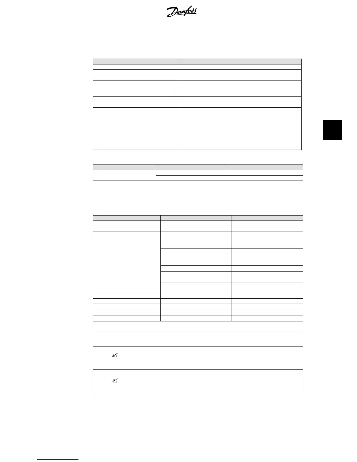
Parameter Specification
Temperature
−25 °C - +60 °C (>45 °C derating)
Environmental class according to IEC IEC60721-3-3
3K6/3B3/3S3/3M2
Air quality ISA S71.04-1985
Level G2 (at 75 % RH)
Coastal, heavy industrial and farmer areas Must be measured and classified acc. to ISA S71.04-1985
Vibration 1G
Ingress protection class 54
Max. operating altitude 3000 m above sea level.
PELV protection is effective up to 2000 m above sea level only.
Installation Avoid constant stream of water.
Avoid direct sunlight.
Ensure adequate air flow.
Mount on non-flammable surface.
Mount upright on vertical surface.
Prevent dust and ammonia gases.
Table 5.3: Conditions for Installation
Parameter Condition Specification
Wall Plate Hole diameter 30 x 9 mm
Alignment Perpendicular ± 5° all angles
Table 5.4: Wall Plate Specifications
5.4.
Cable Requirements
Cable Condition Specification
AC 5 wire cable Copper
Outer diameter 18-25 mm
Insulation strip All 5 wires 16 mm
Max. recommended cable length
TripleLynx
8k and 10k
2.5 mm
2
21 m
4 mm
2
34 m
6 mm
2
52 m
10 mm
2
87 m
Max. recommended cable length
TripleLynx
12.5k
4 mm
2
28 m
6 mm
2
41 m
10 mm
2
69 m
Max. recommended cable length
TripleLynx
15k
6 mm
2
34 m
10 mm
2
59 m
PE Cable diameter at least as phase cables
DC Max. 1000 V, 12 A
Cable length
4 mm
2
- 4.8 Ω /km
< 200 m*
Cable length
6 mm
2
- 3.4 Ω /km
>200-300 m*
Mating connector Multi-contact PV-ADSP4./PV-ADBP4.
* The distance between inverter and PV array and back, plus the summarised length of the cables used for
PV array installation.
Table 5.5: Cable Requirements
Note:
Avoid power loss in cables of more than 1 % of nominal inverter rating.
Note:
In France, observe the UTE C 15-712-1 and NF C 15-100 requirements.
5. Technical Data
L00410309-07_02 25
5