VLT® 2800 Series
Installation
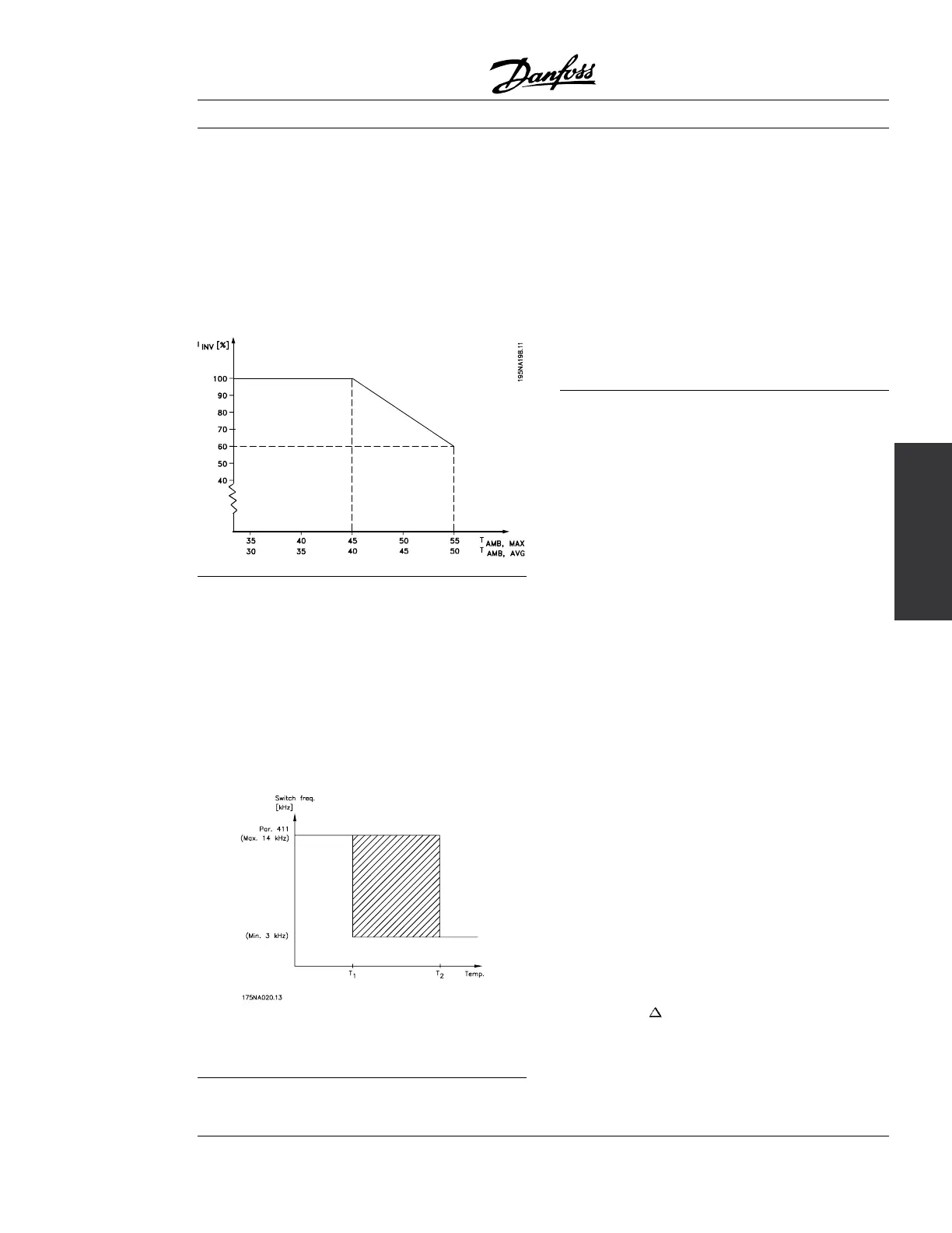
■ Special conditions
■ See Derating for ambient temperature.
The ambient temperature (T
AMB,MAX
) is the maximum
temperature allowed. The average (T
AMB,AVG
)
measured over 24 hours, must be at least 5 °C
lower. If the variable frequency drive operates at
temperatures above 113 °F (45 °C), a derating of
the rated output current is necessary.
■ Temperature-related switching frequency
This function ensures the highest possible switching
frequency without the adjustable frequency drive
becoming thermally overloaded. The internal
temperature determines the switching frequency based
on the load, the ambient temperature, the supply
voltage and the cable length. The function ensures that
the drive automatically adjusts the switching frequency
between the minimum and maximum switching
frequency (parameter 411), see drawing below.
When using the LC filter the minimum switch
frequency is 4.5 kHz.
■ Derating for long motor cables
The adjustable frequency drive has been designed
for a 240 ft (75 m) unscreened/unarmored cable
or a 80 ft (25 m) screened/armored cable and
a motor cable with a rated cross-section. If a
cable with a larger cross-section is required, it is
recommended to reduce the output current by
5% for each step that the cable cross-section is
increased. (Increased cable cross-section leads
to increased capacitance to ground, and thus to
an increased ground leakage current.)
■ VLT 2800 start-up
Pre-installation checks
1. Compare drive model number to what was ordered.
2. Ensure each of following are rated for same voltage:
•Drive
•Powerline
• Motor
3. Record following motor data:
• Voltage
• Frequency
• Full load current
• Full load speed
• Power - convert HP to kW (See conversion table
in parameter 102, Motor Power, in this manual.)
4. Ensure that rated drive current is equal to or
greater than total full load current.
• Drive can be at most onesizesmallerthanmotor.
• For multiple motor operations, add full load
current ratings of all motors.
• If drive rating is less than motor(s), full motor
output cannot be achieved.
5. Check motor wiring:
• Any disconnect between drive and motor
should be interlocked to drive safety interlock
circuit to avoid unwanted drive trips.
• No power factor correction capacitors can be
connected between drive and motor.
• Two speed motors must be wired
permanently for full speed.
•Y-start,
-run motors must be wired
permanently for run.
MG.28.A8.22 - VLT is a registered Danfoss trademark
29
 Loading...


