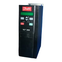
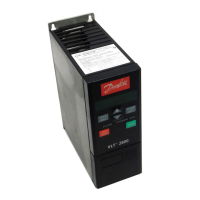
Do you have a question about the Danfoss VLT 2840 and is the answer not in the manual?
Essential safety instructions and warnings for unit installation and operation.
Covers mechanical, electrical power, and control cable installation procedures.
Instructions for starting the motor and critical safety regulations.
Key safety rules and warnings concerning high voltage and equipment protection.
Critical safety information to prevent accidental motor starts.
Explanation of control keys like QUICK MENU, CHANGE DATA, STOP/RESET, and START.
Selecting operating configuration (open/closed loop) and torque characteristics.
Setting motor power, voltage, frequency, current, and speed from nameplate data.
Algorithm for automatically measuring motor parameters like stator resistance.
Configuring thermal motor protection using thermistors or electronic thermal relay (ETR).
Setting output frequency direction, low limit (fMIN), and high limit (fMAX).
Defining the reference signal range (positive/negative) and setting min/max limits.
Setting current limits and configuring warnings for low/high current and frequency.
Assigning functions like Start, Stop, Jog, etc., to digital input terminals.
Selecting brake function (resistor, AC, load sharing) and configuring reset modes.
Optimizes pump control at low flow for energy savings and reduced wear.
Protects pump and motor by stopping operation during dry run conditions.
Includes high voltage warnings, earthing, and extra protection measures.
Ensures electromagnetic compatibility through proper cable and connection methods.
Installation of safety clamp for isolation and fitting of pre-fuses for mains supply.
Guidance on connecting mains supply and motor terminals, including wiring schemes.
Configuring motor thermal protection and ensuring proper earth connection.
Overview of warnings and alarms, their codes, and reset procedures.
How the converter protects against motor overload and power module overtemperature.


