79MG.30.A7.02 - VLT
®
is a registered Danfoss trademark
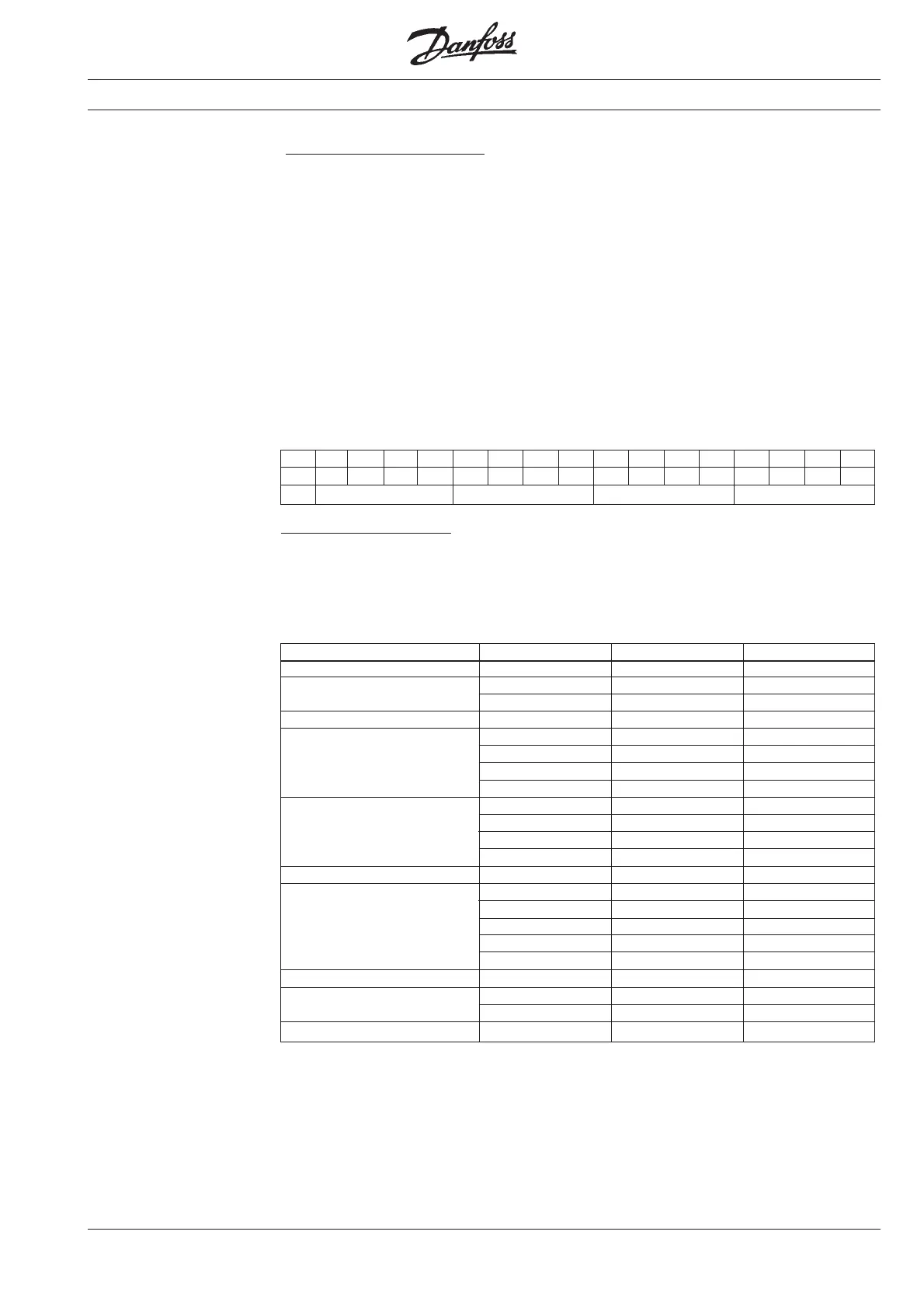
Bit 15 14 13 12 11 10 09 08 07 06 05 04 03 02 01 00
0/10000101110000111
ASCII @ K H G
Communication example:
A VLT
®
frequency converter with address 1
is to have a start signal and speed refer-
ence equivalent to 40 Hz. A start signal is
given with the help of the control word (see
example on p. 77), and the speed refer-
ence is written to parameter 516, bus
reference, 80% equivalent to 40 Hz, the
maximum frequency being 50 Hz. This
gives the following telegram structure:
Telegram from master (PC or PLC) to frequency converter
Function Byte no. ASCII character Decimal value
Start byte 1 < 60
2048
3149
Control character 4 U 85
5O79
6G71
7D68
8@64
9048
10 5 53
11 1 49
12 6 54
Sign 13 + 43
14 0 48
15 0 48
16 0 48
17 8 56
18 0 48
Comma 19 0 48
20 0 48
21 7 55
Stop byte 22 > 62
Data value
Check sum
Check sum: Byte 2-19 = 1007 reduced to 07
Address
Control/status word
Parameter no.
Groups
Bit 15, Timers OK/above limit:
Bit 15 = “0” means that the timers for
respectively thermal motor protection
(described on p. 130) and thermal VLT
®
protection have not exceeded 100%. Bit 15
= “1” means that one of the timers has
exceeded 100%.
Example:
The status word below states that the
motor is running at the required speed
reference but outside the defined fre-
quency range and therefore bit 10 = “0”
(out of frequency range) and bit 07 = “1”
(warning). Voltage, current and timers are
OK.
Serial data interface,
group 5..
(continued)
Artisan Technology Group - Quality Instrumentation ... Guaranteed | (888) 88-SOURCE | www.artisantg.com