14-22 Operation Mode
Option: Function:
6. Carry out various tests.
7. The results are displayed on the
LCP, and the adjustable frequency
drive moves into an infinite loop.
8.
Parameter 14-22 Operation Mode is
automatically set to normal
operation. Perform a power cycle to
start up in normal operation after a
control card test.
If the test is OK
LCP readout: Control card OK.
Disconnect the line power supply and
remove the test plug. The green LED on the
Control Card lights up.
If the test fails
LCP readout: Control card I/O failure.
Replace the adjustable frequency drive or
control card. The red LED on the control card
is turned on. Test plugs (connect the
following terminals to one another): 18 - 27 -
32; 19 - 29 - 33; 42 - 53 - 54
130BA097.12
FC 302
FC 301
FC 301 &
FC 302
1312 18 37322719 29 33 20
5039 42 5453 55
191812 13 203327 32
Figure 6.13 Control Card Test Connections
Select [2] Initialization to reset all parameter
values to default settings, except for
15-03 Power-ups, 15-04 Over Temps, and
15-05 Over Volts. The adjustable frequency
drive resets during the next power-up.
Parameter 14-22 Operation Mode also reverts
to the default setting Normal operation [0].
[0]
Normal
operation
[1] Control card
test
14-22 Operation Mode
Option: Function:
[2] Initialization
[3] Boot mode
14-50 RFI 1
Option: Function:
NOTICE!
This parameter is only available for FC 302. It is
not relevant to FC 301 due to different design
and shorter motor cables.
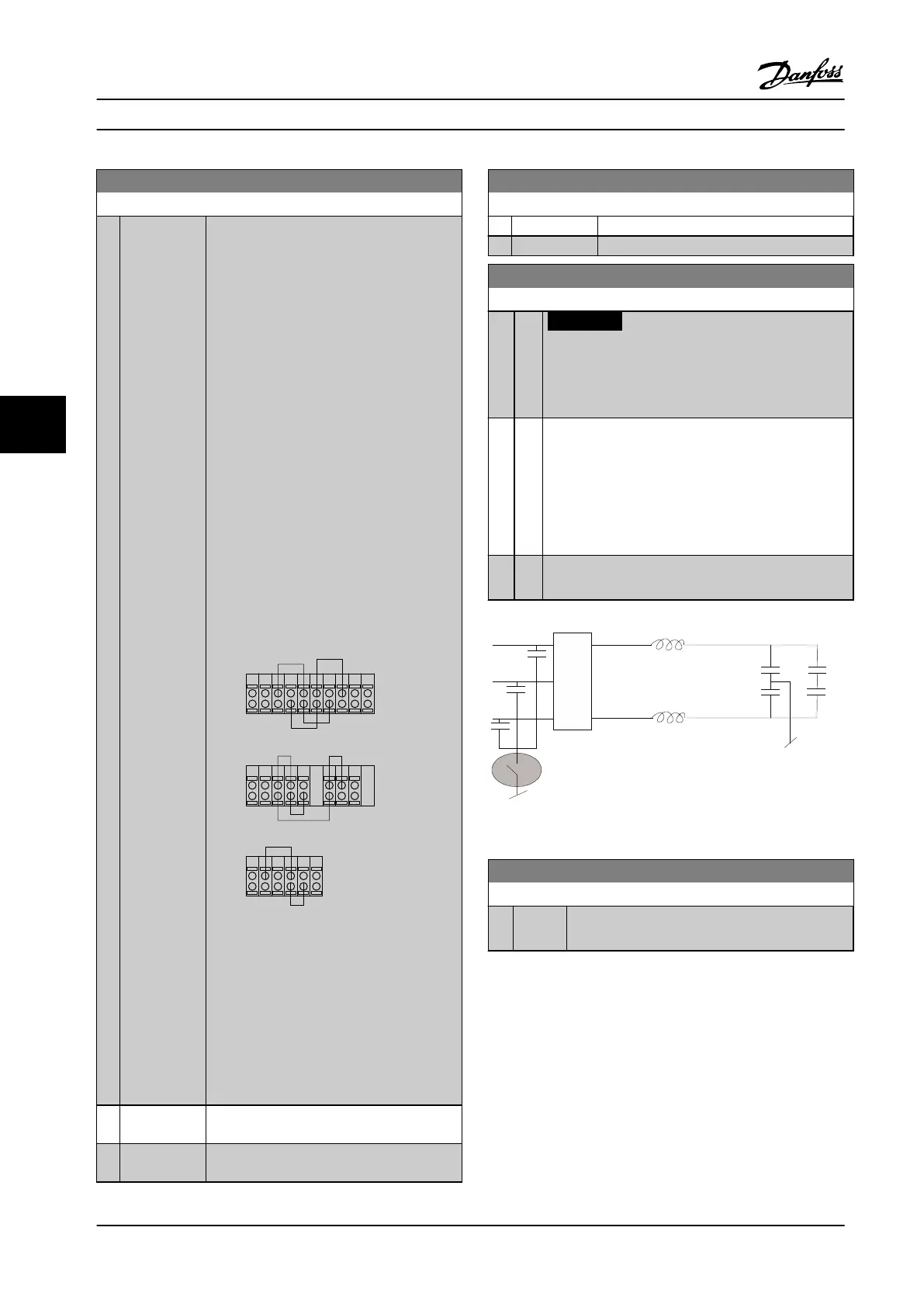
[0] Off
Select [0] Off if the adjustable frequency drive is fed by
an isolated line power source (IT line power).
If a filter is used, select [0] Off during charging to
prevent a high leakage current making the RCD switch.
In this mode, the internal RFI filter capacitors between
chassis and the line power RFI filter circuit are cut-out
to reduce the ground capacity currents.
[1] On
Select [1] On to ensure that the adjustable frequency
drive complies with EMC standards.
Figure 6.14 RFI Filter Diagram
15-43 Software Version
Range: Function:
0 * [0 - 0 ] View the combined SW version (or ‘package
version’) consisting of power SW and control SW.
Programming Instruction Manual
76 Danfoss A/S © Rev. 2014-02-07 All rights reserved. MG37A222
66
 Loading...


