3.3
Installation in Combination with VLT
®
PTC Thermistor Card MCB 112
NOTICE
Combination of VLT
®
PTC Thermistor Card MCB 112 and
STO function is only available for VLT
®
HVAC Drive FC
102, VLT
®
AutomationDrive FC 302, and VLT
®
AutomationDrive FC 301 enclosure type A1.
VLT
®
PTC Thermistor Card MCB 112 uses Terminal 37 as its
safety-related switch-off channel.
•
Ensure that the output X44/12 of MCB 112 is
AND-ed with the safety-related sensor (such as
emergency stop button, safetyguard switch, etc.)
that activates STO. This means that the output to
STO terminal 37 is HIGH (24 V) only if both the
signal from MCB 112 output X44/12 and the
signal from the safety-related sensor are HIGH. If
at least 1 of the 2 signals is LOW, then the output
to terminal 37 must be LOW too.
•
Ensure that the safety device with AND-logic
complies with the needed safety level.
•
Short-circuit protect the connection from the
output of the safety device with safe AND-logic
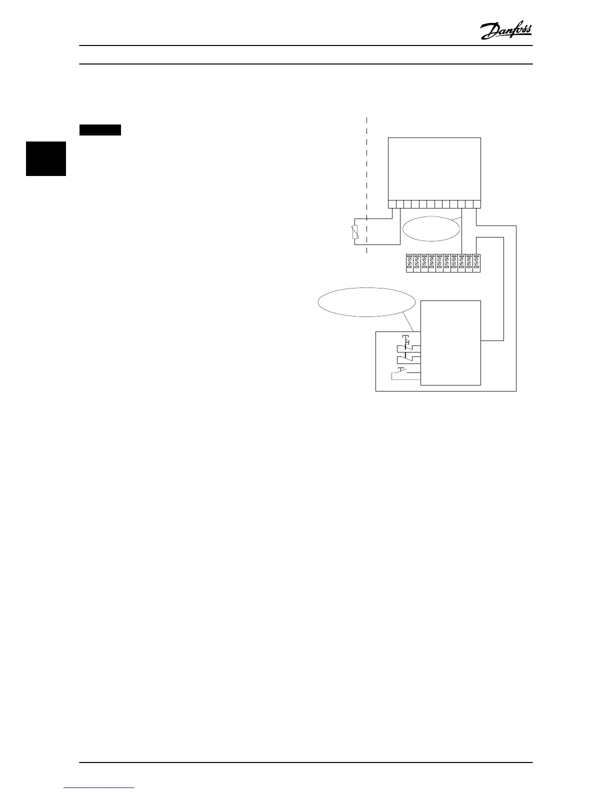
to the STO terminal 37, see Illustration 3.3.
Illustration 3.3 Combination of an STO Application and an
MCB 112 Application
Illustration 3.3 shows a Restart input for the external safety
device. This means that in this installation, 5-19 Terminal 37
Safe Stop can be set to value [7] PTC 1 & Relay W or [8] PTC
1 & Relay A/W. Refer to VLT
®
PTC Thermistor Card MCB 112
Operating Instructions for further details.
Installation Operating Instructions
8 Danfoss A/S © 09/2014 All rights reserved. MG37D202
33

 Loading...


