21
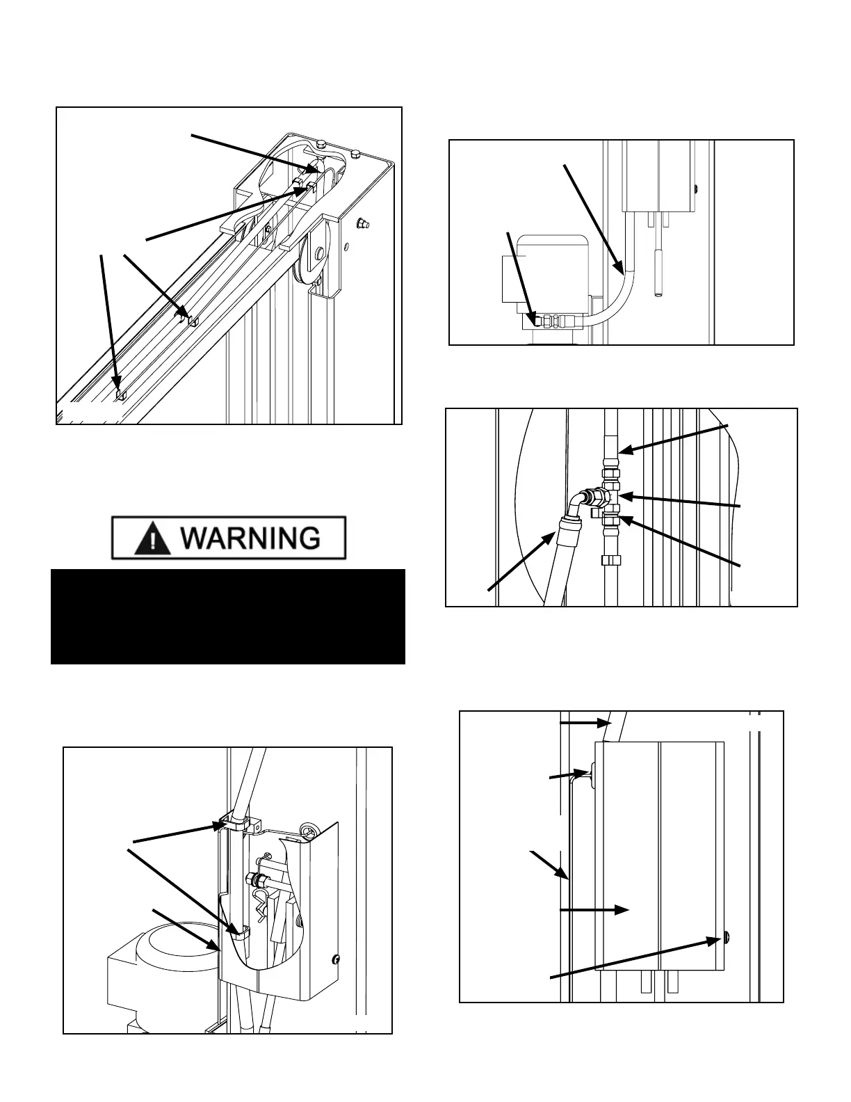
3. Route wire up through Column and across Overhead
Assembly through hole in Overhead Assembly into the
Microswitch box. (See Fig. 12.3)
STEP 13
(Installing Power Unit Hose
and Power Side Safety Cover)
1. With Power Side Safety Cover loosely positioned,
route Power Unit Hydraulic Hose through clips in Power
Side Safety Cover. (See Fig. 13.1)
2. Install the Elbow Fitting w/ O-ring into the Hydraulic
Pressure Port of the Power Unit. Connect the Power Unit
Hose to the Elbow Fitting (See Fig. 13.2)
3. Connect other end of Power Unit Hydraulic Hose to
the Hydraulic Tee Fitting. (See Fig. 13.3)
4. After Safeties have been adjusted and checked for
proper operation, install and tighten Power Side and Off
Side Safety Cover mounting screws.
(See Fig. 13.4 and 13.5)
Fig. 12.3
Microswitch
Wire
Microswitch
Wire Clips
POWER UNIT HYDRAULIC HOSE MUST BE ROUTED
THROUGH THE HOSE CLIPS IN POWER SIDE
SAFETY COVER. FAILURE TO DO SO CAN RESULT
IN PERSONAL INJURY OR DAMAGE TO THE LIFT.
Fig. 13.1
Route Power
Unit Hydraulic
Hose through
clips in Power
Side Safety
Cover
Safety Cover
Fig. 13.2
Power unit
90° tting with
O-ring
Power unit
hose assembly
Fig. 13.3
Power
Hose
Crossover
Hose
Bulk-
head
tting
Power
Side
Hose
Fig. 13.4
Screw
Screw
Microswitch
Wire
Power unit
hose assembly
Power Side
Safety Cover