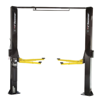
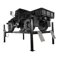
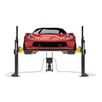
26
STEP 15
(Power Unit Connection)
1. Have a certied electrician run the power supply to
motor. Refer to the data plate found on the motor for
proper power supply and wire size.
RISK OF EXPLOSION!
This equipment has internal arcing or parts that may spark
and should not be exposed to ammable vapors. Motor
should not be located in a recessed area or below oor
level. NEVER expose motor to rain or other damp
environments. DAMAGE TO MOTOR CAUSED BY
WATER IS NOT COVERED UNDER WARRANTY.
STEP 16
(Final Adjustments / Post-Installation Checklist)
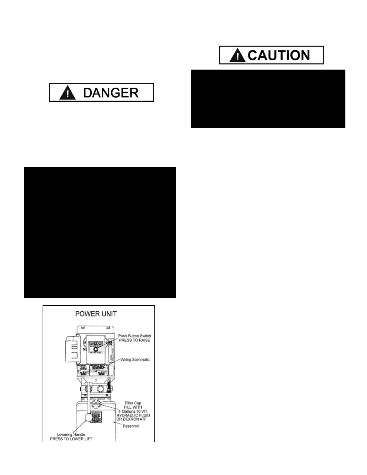
1. Check the Hydraulic Fluid Reservoir; it must be full of
approved Hydraulic Fluid or automatic transmission uid.
You can harm the motor by running it without enough
uid.
2. Apply light axle grease to the inside of the posts where
the slide blocks glide.
3. Make sure the Power Unit is getting power from the
power source.
4. Check the Hydraulic System for leaks.
5. Make sure both Columns are properly plumbed,
shimmed, and stable.
6. Make sure all Cables are properly positioned within the
grooves of ALL Cable Sheaves. Make sure all Cable Sheave
Retaining Clips/Pins are secure.
7. Make sure that all safety locks are cleared and free.
8. Make sure both Safety Assemblies are connected and
working normally.
9. Make sure all Safety Locks are clear and free.
10. Continue to press the button to raise the Lift until the
Cables are taut and the Lift starts to move.
11. Check to see that all the Anchor Bolts are properly
torqued.
12. Perform an Operational test with a typical Vehicle.
NOTE:
CAUTION NEVER OPERATE THE MOTOR ON LINE
VOLTAGE LESS THAN 208V. MOTOR DAMAGE
MAY OCCUR WHICH IS NOT COVERED UNDER
WARRANTY. HAVE A CERTIFIED ELECTRICIAN
RUN APPROPRIATE POWER SUPPLY TO MOTOR.
SIZE WIRE FOR 25 AMP CIRCUIT. SEE MOTOR
OPERATING DATA TABLE. USE SEPARATE CIRCUIT
FOR EACH POWER UNIT. PROTECT EACH CIRCUIT
WITH TIME DELAY FUSE OR CIRCUITBREAKER.
FOR SINGLE PHASE 208-230V, USE 25 AMP FUSE.
THREE PHASE 208-240V, USE 25 AMP FUSE. FOR
THREE PHASE 400V AND ABOVE, USE 15 AMP
FUSE. ALL WIRING MUST COMPLY WITH NECK AND
ALL LOCAL ELECTRICAL CODES.
Fig 15.1
DURING THE START-UP PROCEDURE, OBSERVE
ALL OPERATING COMPONENTS AND CHECK
FOR PROPER INSTALLATION AND ADJUSTMENT.
DO NOT ATTEMPT TO RAISE VEHICLE
UNTIL A THOROUGH OPERATIONAL CHECK
HAS BEEN COMPLETED.