D4-9 / D4-9X Four-Post Lifts 44 P/N 5900251 — Rev. A1— August 2021
Installing the Return Line
The Return Line takes excess Hydraulic Fluid coming out of the Hydraulic Cylinder and sends it back
into the Fluid Reservoir on the Power Unit.
The Return Line is a single piece of ¼ inch, black Tubing with a Compression Elbow Fitting (5550089)
on each end. You need to cut a piece of the supplied Tubing to create the Return Line.
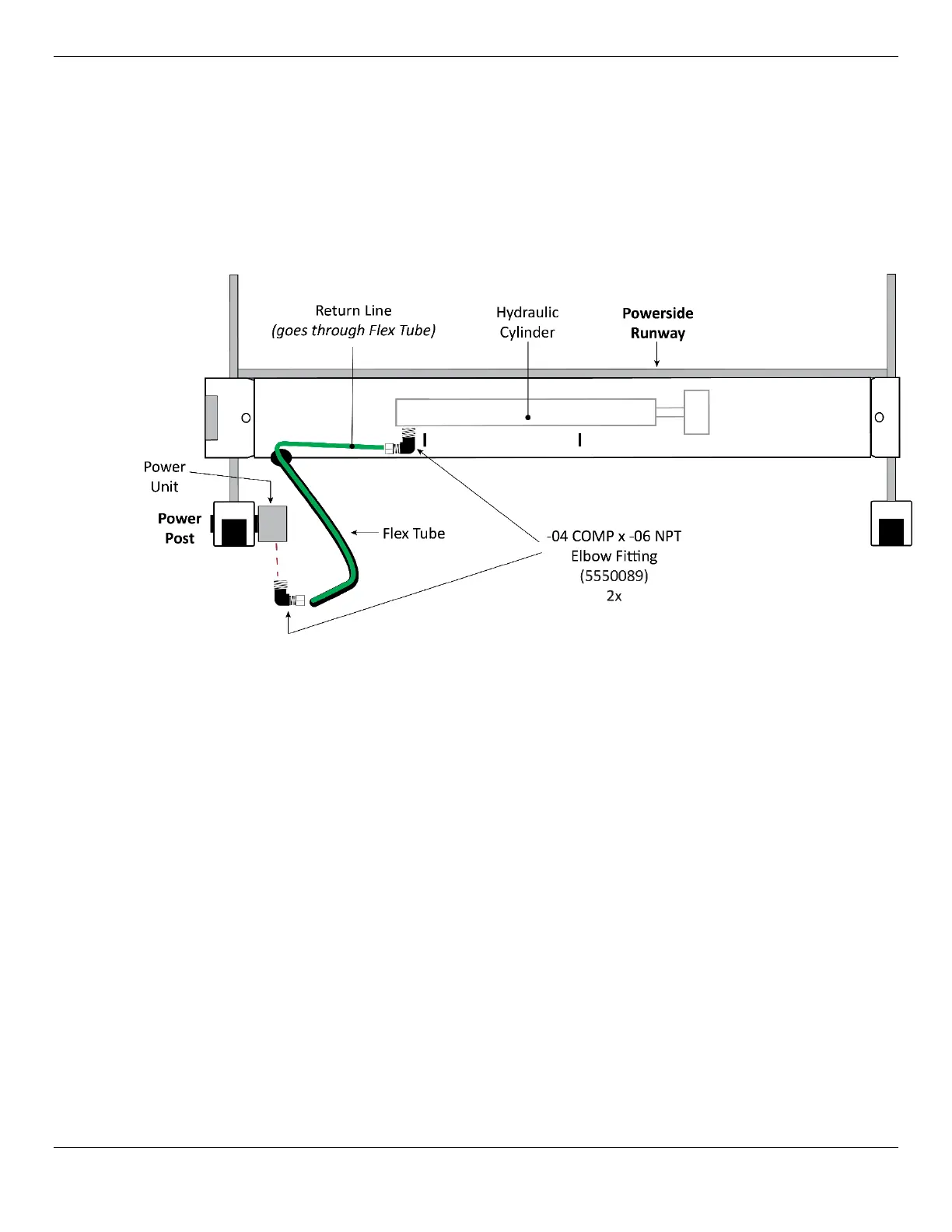
The following illustration shows how to route the Return Line from the Hydraulic Cylinder to the Power
Unit.
Top View of the Powerside Runway. Drawing not to scale. Some components exaggerated for clarity.
To install the Return Line:
1. Measure from the Hydraulic Return Port on the Hydraulic Cylinder to the Hydraulic Return Port on
the Power Unit, then cut a piece of Tubing of appropriate length from the supplied roll of Tubing.
NOTICE The Return Line is going to be routed through the Flex Tube, so take that into account. It
is better to make the Tubing piece a little too
long
rather than a little too short.
2. Route the Tubing through the Flex Tube.
3. Locate the Hydraulic Return Port on the Power Unit and remove the Shipping Plug.
NOTICE The Hydraulic Return Port is commonly labeled either T1/T2 or CV1/CV2.
4. Connect the NPT end of the Compression Elbow Fitting to the Power Unit, then connect the other
end of the Elbow Fitting to the Return Line coming out of the Flex Tube.
Use Liquid Thread Sealant on NPT Threads only.
Refer to Working with Compression Fittings and Tubing for instructions.
5. Remove the Shipping Plug from the Hydraulic Return Port on the Hydraulic Cylinder.
6. Connect the NPT end of the second Compression Elbow Fitting to the Hydraulic Return Port, then
connect the other end to the Return Line.
Use Liquid Thread Sealant on NPT Threads only
.