DB-70 Automatic Wheel Balancer 19 P/N 5900261 — Rev. A1 — January 2021
⚠ CAUTION The Voltage Selector Switch
must
match the power source. If you plug the unit in
to 110 VAC power when the Switch is set to 220V or you plug the unit in to 220
VAC power when the Switch is set to 110V, you void your warranty and you could
severely damage the Tire Changer.
5. Plug in the Tire Changer to a 220 VAC outlet.
6. Test the unit to make sure it is working normally.
Additional electrical information:
You must ground the Tire Changer
.
Damage caused by improper electrical installation (such as not grounding the unit) voids the
warranty.
⚠ WARNING Disconnect power
before
performing
any
troubleshooting or maintenance. Make
sure the unit cannot be re-energized until you are done. This equipment has internal
arcing or sparking parts that should not be exposed to flammable vapors. The unit
must
not
be located in a recessed area or below floor level.
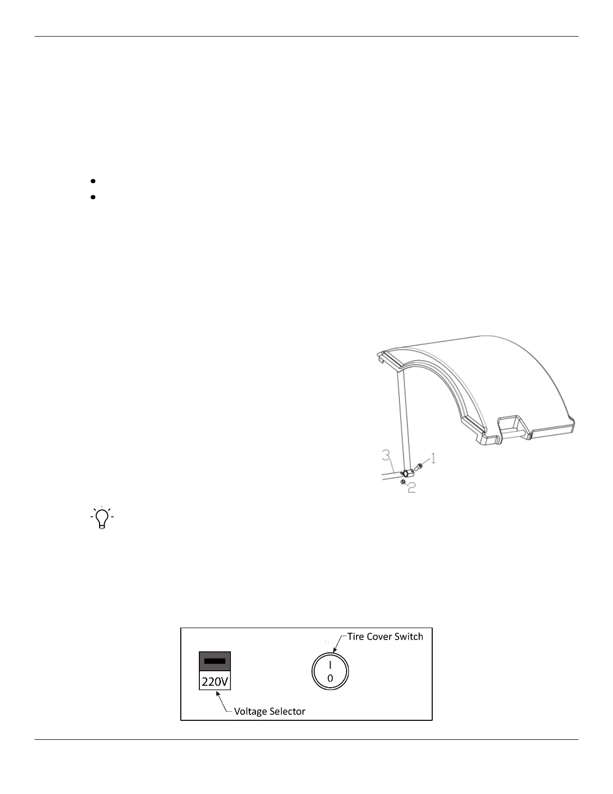
Installing the Tire Cover
The Tire Cover is a large molded plastic cover with a steel
tube frame designed to protect the operator from the Tire
while it is in motion.
1. Locate the rotating shaft near the bottom of the
Balancer toward the rear on the shaft side of the
Balancer.
2. Mate the Tire Cover Support Bar to this shaft and
insert one M10 x 45 Hexagonal Cylindrical Head
Machine Screw (1) into the assembly at the bottom
of the Balancer on the same side as the Balancer
Matcher and Shaft (3).
3. Secure with an M10 Lock Nut (2).
Tip The Tire Cover position can control the Balancer’s test start. This feature may be disabled
by an on-off switch located on the back of the Balancer between the 110/220V operation switch and
the power cord.
• In the
position, the Balancer will start a test cycle when the Tire cover is closed and stop it
when open.
• In the
position the Tire cover must be manually closed and the test cycle begun by pressing
on the front panel.