18
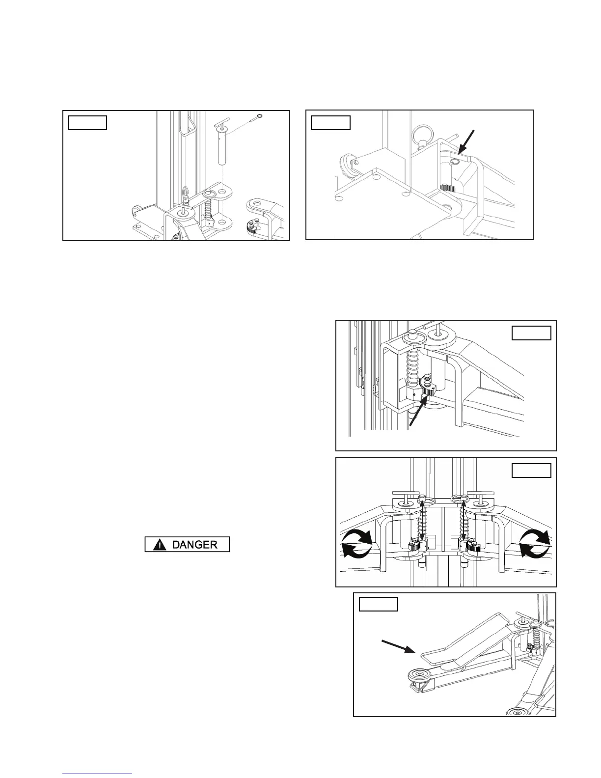
STEP 9
INSTALLING THE LIFT ARMS
Fig. 20
Quick Release Pin
1. Place the lift arm assembly on the lift heads. Install the lift head pins (P/N 17157026) into the lift head and through
the holes in the arm assembly. Install the quick release pin into place on the arm pin. S
P/N 17157026
P/N 17157026
Fig. 21
©2018 DANNMAR EQUIPMENT. ALL RIGHTS RESERVED.
2. Loosen the arm restraint gear ring bolts and adjust the arm restraint gears so that the teeth on the gear ring mesh
smoothly with the teeth on the gears of the arm gear stop. S
1. Raise the lift high enough so that the arm gear stops. Attempt to automatically engage the restraint gears on the
arms.
3. Tighten the gear ring bolts
4. Verify the operation of the arm gear stops by pulling up on the
key ring of the arm gear stops. Pivot the arms back and forth
and test the operation of the arm gear stops in various positions.
When releasing the arm gear stop, the pin should drop and the
gears should engage. S
6. Adjust the gear ring on the arm as necessary to ensure smooth
operation and solid engagement of all four arm restraint pins.
Each arm restraint assembly must be inspected and adjusted
as needed before each and every time the lift is operated. Do
not operate the lift if any of the four arm restraint systems are
not functioning properly. Replace any broken components or
components with broken teeth only with authorized or approved
replacement parts.
5. Ensure that the arms do not move when a force of at least
100 pounds is applied laterally to the fully extended arms. If
they move, readjust the arm restraint gear ring and/or tighten
the arm restraint gear ring bolts.
Fig. 22
Arm Restraint Gear
Fig. 23
CE Users: Installing the Arm Foot Guards
1. Install the Foot Guards. They are directional (left/right sided)
and will only t properly on one side or the other.
S
Fig. 24
Foot Guard
P/N 17158151
17158152