46210/46220-0998 <90-00036> PAGE 11
4. Set switches S1, S2, and S3 (refer to Fig. 9 and Tables A-D).
NOTE: If the unit is communicating in TBOS protocol through the
communications ports, use Table 3 to set the switches on S1. If
the unit is communicating in DCP, DCPF, or DCM protocol
through the communications ports, use Table 4.
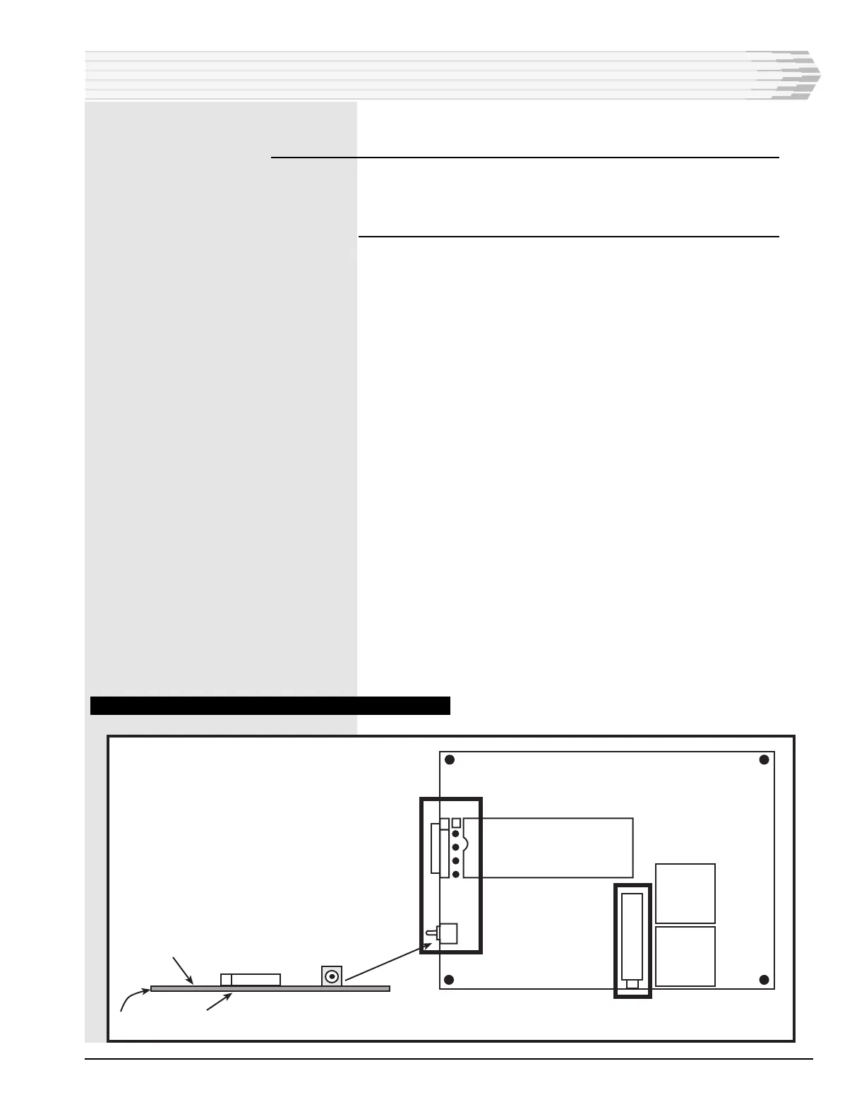
5. If the unit is equipped with a 202 Modem subassembly, set the
straps on X1 (refer to Figs. 9 and 10).
Place the straps across pins 2-3 and 4-5 to adjust the transmit out-
put between -1 and -20 dBm.
-or-
Place the straps across pins 1-2 and 3-4 to adjust the transmit out-
put between -20 and -40 dBm.
6. If the unit is equipped with an RS-232 subassembly, set strap X1
(refer to Figs. 9 and 11).
Place the strap across pins 1 and 2 to use Data Carrier Detect
(DCD) as a handshaking line.
-or-
Place the strap across pins 2 and 3 to keep DCD always active.
7. If the unit is equipped with an RS-232 subassembly, set strap X2
(refer to Figs. 9 and 11).
Place the strap across pins 1 and 2 to use Clear to Send (CTS) as a
handshaking line.
-or-
Place the strap across pins 2 and 3 to keep CTS always active.
8. This section complete.
FIG. 10 - 202 MODEM SUBASSEMBLY COMPONENT LOCATION
INSTALLATION
X1
1
S1
R8
S1
Test
Component Side
Solder Side
Normal
PC Board