46210/46220-0998 <90-00036> PAGE 19
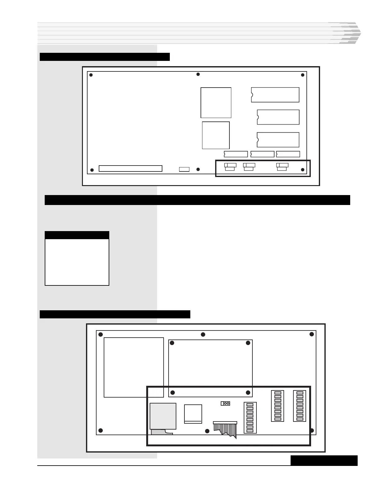
FIG. 12 - CPU BOARD COMPONENT LOCATION
WIRING
Wire the power, alarm inputs, control outputs, and the commu-
nications ports as described below. Connector P1 is not used.
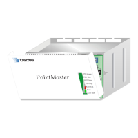
1. On the power supply board, wire negative battery (-21 to -56 VDC)
and ground to connector TB1 (refer to Fig. 13). Remove the connec-
tor for easier access. Do not turn on the power until instructed.
2. Wire an external fuse alarm indicating device, such as a light or
bell, to the ALM output of TB1 (optional). When the fuse fails, the
external device operates as well as the ALARM LED on the front
panel.
3. Push the power supply and CPU boards back into place and close
the unit.
FIG. 13 - POWER SUPPLY BOARD COMPONENT LOCATION
INSTALLATION
NOTE:
Chassis ground, if
desired, can be
connected to the
screw in the front,
right-hand corner
of the top panel.
F1
TB1
P1
S1
S2
S3
AUX LED
1
3
-48
ALM
GND
RS-232 OR 202
SUBASSEMBLY
CONTINUED . . .
A80-00504-00
REV.
X2
1
X1
1
X3
1