PAGE 20 46210/46220-0998 <90-00036>
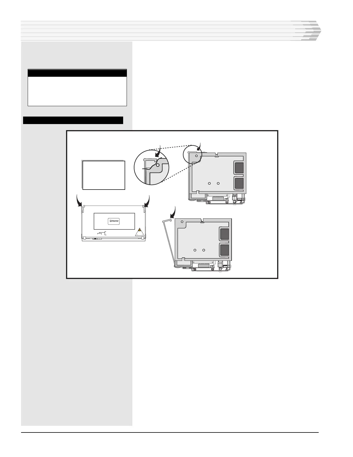
4. Open the plastic cover (refer to Fig. 14).
5. Wire the alarm inputs (refer to Fig. 15 or the template inside the
plastic cover).
There are two pins for each alarm input. One is for ground and the
other is for the alarm input. The dark-colored columns are grounds
and are wired together. Wire one of the ground pins to signal
ground on your equipment.
Leave enough slack in the wires to open the unit easily.
FIG. 14 - OPENING PLASTIC COVER
6. Wire the control outputs of any 46220 units (refer to Fig. 15 or the
template inside the plastic cover).
There are two pins for each normally open relay. Wire the pins for
either a battery or ground output when the relays are closed. Pin
pairs for the relays are A-B, C-D, E-F, G-H, J-K, L-M, N-P, and
R-S.
7. Wire the master and/or auxiliary ports at column 32 (refer to
Fig. 15 or the template inside the plastic cover).
If no communications subassembly is used, pins A-D are the auxil-
iary port connections and pins E-H are the master port connec-
tions.
If an RS-232 or 202 Tone Modem subassembly, pins E-H are the
auxiliary port connections and pins J-S are the master port connec-
tions.
To wire to a Digital Alarm Scanner (DAS) unit, refer to Fig. 16.
7. Wiring complete.
INSTALLATION
Side
View
Closed
To open front panel
for access to wire
wrap pins, lift up
on the tabs on the front
panel. The panel
will swing forward.
Side
View
Open
462xx-xx REV ____
WARNING:
REMOVE fuse
before removing
or inserting module
Use wrist strap
ESD SENSITIVE DEVICE
POWER
ALARM
uP LED
MSTR
AUX
GREEN = RCV
RED = XMT
Front View
NOTE:
All even numbered rows except
32 are connected to digital
ground internally. Connect one of
these pins to signal ground.