Quick Installation Guide H B 51 Hybrid inverter
Rev.1 ©2018 Darfon Electronics Corp. 4 | Page
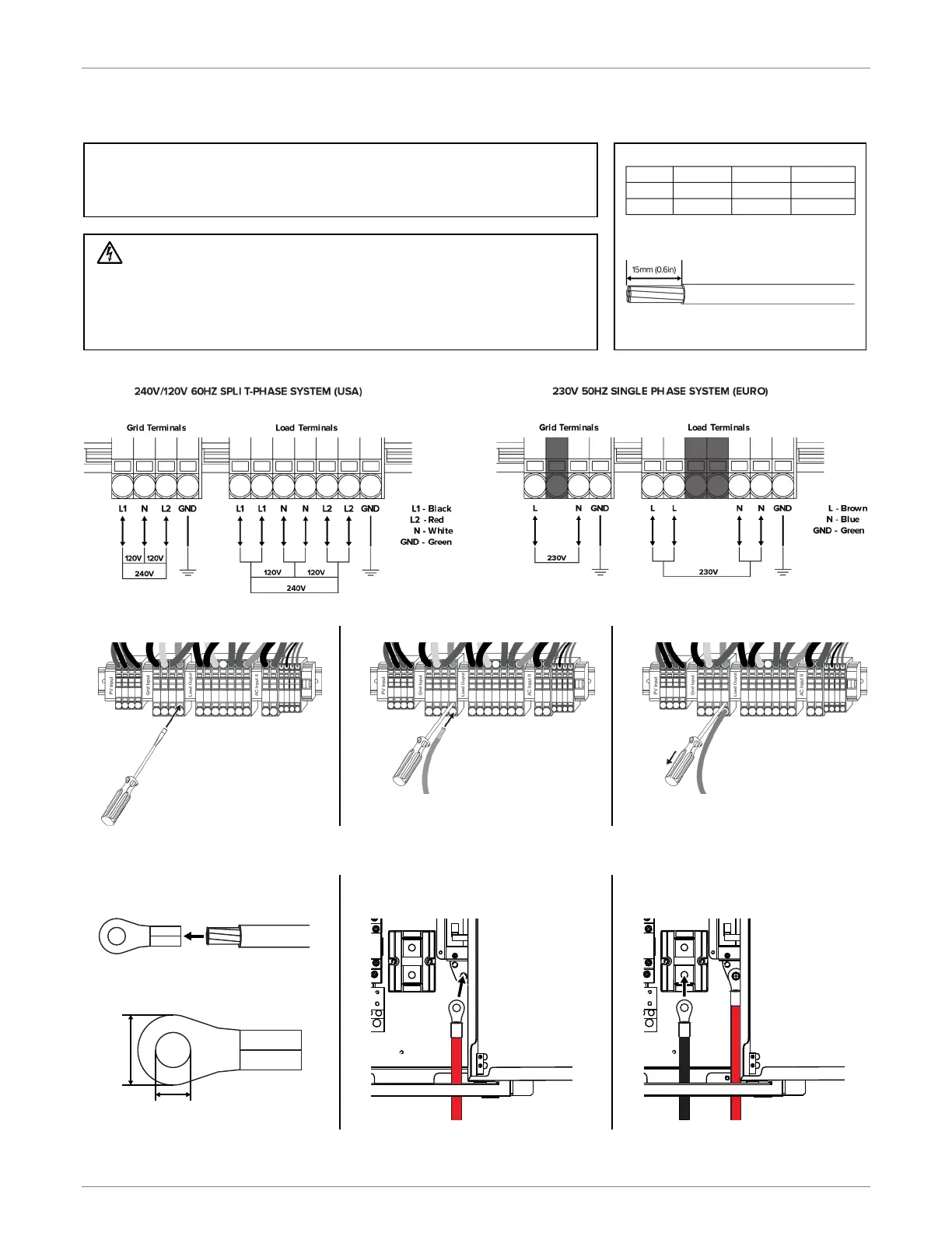
CONNECTIONS
System Types: Quick Disconnect Terminals
Installing Conductors in to the Terminal Blocks
1. Push a screwdriver into terminal.
2. Insert the wire into the terminal.
3. Remove the screwdriver.
Installing the Battery Conductors
1. Crimp or bolt ring lugs to the battery
cables.
2. Connect the red cable to the
positive (+) battery terminal.
3. Connect the black cable to the
negative (-) battery terminal.
8mm
(0.3in)
16mm
(0.6in)
Ring Lug Dimensions
Tor que Val ue:
2 to 3Nm
(18 to 26 in-lb)
Torque Val ue:
2 to 3Nm
(18 to 26
in-lb)
Strip 15mm(0.6in) off the AC wires and
battery cables.
WARNINGS
Make sure the circuit breaker is off before making or modifying any connections.
To prevent the risk of electric shock, make sure the ground wire is properly earthed
before operating this unit whether the grid is connected or not.
To reduce the risk of injury, use the recommended wire/cable size.
Do not apply anti-oxidant substance on battery terminals connections are made.
Order of connections should be Grid, Load, then Battery.
Order of wire connections should be Ground, N, L1, L2.
Connect AC wires according to the labels on the terminal block or your system type.