GB
1. Safety rules
Warning
: Any repairing, fitting or adjustment made from people not qualified is strictly forbidden and in order to avoid any possible
accident, all necessary precautions must been taken (ex: switch off the power supply as well as disconnect batteries). Daspi is not
responsible for possible damages or injuries to people, objects or animals caused by any unauthorized modification of product. Do not
install this product into an explosive place
Keep scrupulously this booklet and include it into the main user manual in a suitable place well known by all the interested people.
2. Model
The control panel MACH4E has been designed for driving 1 operator for automatic barriers and it has an electric clutch. Daspi is not
responsible for any different use of control panel MACH4E
3. List of main components
TR1
Transformer: 230 Vac – 24 Vac
F1
Net protection’s fuse 5A
J2
Terminal for anti-crashing system UDS. It allows the boom to invert the
stroke of 10 cm when an obstacle stops its movement.
F2
Controls protection’s fuse 2A
JP1
Terminals for power supply connection 230 Vac 50 Hz
SW1
Dip-switches for control panel programming
JP2
Terminals for operator and flashing light connection
J1
Receiver terminal
JP3
Terminals for electronic and safety devices connection
Leds showing control panel entrances connections (switching on after power supply has been connected)
DL1
Switching on by START shows that operator is working properly. When flashing it means anomaly or anti-crashing system UDS active.
DL2
Always switched on, it switches off by STOP
DL2
Always switched on, it switches off by PHOTOCELL
DL3
Always switched off, it switches on by START
DL3
Always switched on, it switches off by OPENING LIMIT SWITCH
DL4
Always switched on, it switches off by control safety device
“COSTA”
DL4
Always switched on, it switches off by CLOSING LIMIT SWITCH
Check again the connections and the devices if the above led don’t correspond
4. Control panel programming and adjusting
The programming of dip switches must be made with control panel switched off
SW1 ON OFF
1
It cancels control START during opening (residential system) Control START always active. if set during opening it stops the
operator
2
It sets automatic shutting of barrier with time adjustable by
trimmer R2
Automatic shutting not working.
3
Photocells working in opening. With an obstacle the barrier stops;
it starts again opening after the obstacle has been removed.
Photocells working only in closing. With an obstacle the barrier
stops and re-open
4
It sets a slowing down system of 2 sec. after touching the limit
switches
It sets a slowing down system of 1 sec. after touching the limit
switches
Adjusting of trimmers: R1 electric clutch – R2 Break – R3 Working time
R1 – POWER R2 – BREAK R3 – WORK
Maximum and minimum pushing power of motor. It must
be checked periodically and adjusted following to the
actual norms.
It counts the time of break
after opening and before
closing.
It counts the working time either in opening and
closing. Time must be always adjusted 2-3
seconds more than real movement time of boom
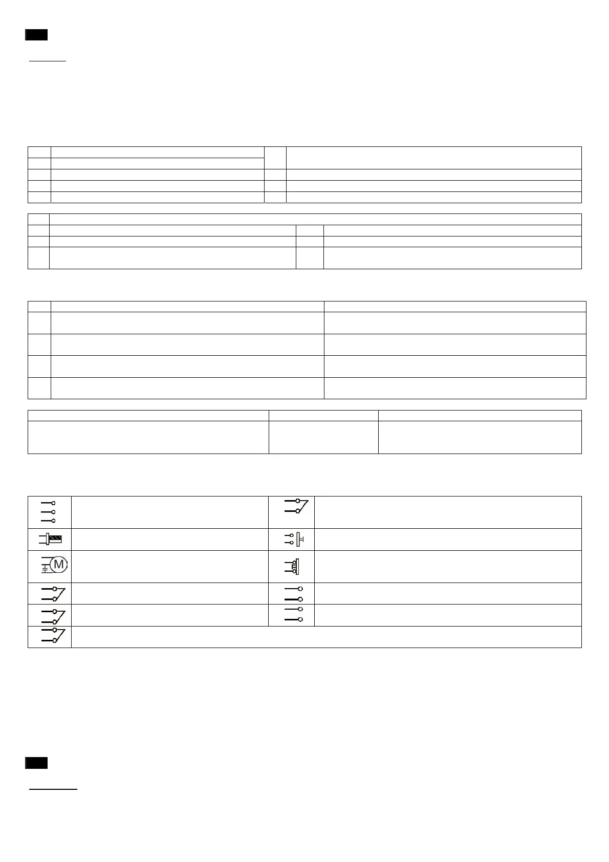
5. Terminals descriptions
Join with a bridge the N.C. (normally closed) entrances you don’t used
If you are using more contacts N.C. on same entrance, they must be connected in set. If you are using more contacts N.O. on same
entrance, they must be connected in parallel
1
2
3
Entrances 1 and 2 for power supply 230 Vac 50
Hz
Entrance 3 for earth connection
14
13
Entrance for safety face device. During opening it stops the
movement and re-starts closing for 10 cm. Contact N.C.
4
5
Entrances for flashing light 220 Vac max. 25
Watt
14
15
Entrance START. If set during opening it stops the movement; if
set during closing invert the movement. Contact N.O.
6
7
8
Motor exit.
6 Common – 7 Open – 8 Close
Capacitor to terminals 7-8
14
16
Entrance STOP. If set it stops any movement and cancel the
automatic shutting. Contact N.C.
9
10
Entrance for limit switches close. It controls
slowing down during closing Contact N.C.
17
18
Exit 24 Vac for external devices as well as extra photocells
9
11
Entrance for limit switches open. It controls
slowing down during opening Contact N.C.
19
20
Entrance for antenna: 19 hot pole – 20 copper cable
14
12
Entrance for photocells. During closing they stop the barrier and re-start opening.
Contact N.C.
6. Testing
To be made with boom at 45° position and only after installing the safety devices required from actual rules in order to reduce
any risk.
• Check all motor connections remembering that first operation made by the control panel is an opening. If barrier closes invert
connections 7-8
• Check the limit switches function remembering that by touching boom doesn’t stop but starts slowing down. It will stop by
mechanical stoppers
• Check whether all safety devices installed are working properly in order to reduce any risk.
• All people in charge of the automation must be trained about the safety devices, controls and dangerousness of system
• Fill up technical booklet and carry out the obligations required from actual rules and norms
E
1. Normas de seguridad generales
ATENCIÓN
: Está prohibido efectuar mantenimiento o reparaciones de las instrumentaciones por parte de personal sin califica y en el
caso no hayan sido tomadas todas las precauciones para evitar accidentes: alimentación eléctrica desconectada (incluidas posibles
baterias de emergencia). Con cualquiera utilización no prevista por este manual de instrucciones y/o con cada modificaciones arbitraria
 Loading...