19 • Air Cooled Condenser User Manual
full. The sight-glass on outdoor receivers will be dicult to observe however, this step is required for
proper charging.
WARNING: When adding refrigerant through the suction line it is imperative that the
refrigerant is meter carefully to the compressor. Charging a liquid into the suction line
too rapidly can cause damage to the compressor.
Units with dual refrigerant circuits should have both compressors running. The unit should be al-
lowed to stabilize for 20 minutes before meaningful measurements can be recorded.
After the system is allowed to stabilize, the superheat at the compressor suction line (at least 6
inches away from the compressor) should be 8 to 15°F. For system with electronic expansion
valves, the superheat setpoint is defaulted at 6°F and should be between 5 to 10°F. Remove the
block from the condenser coil. If the ambient air temperature while charging is below 60°F, some of
the refrigerant will be backed up in the condenser coil, causing the liquid level in the receiver to drop.
NOTE: Charging to a full liquid line sight-glass should never be the sole means of de-
termining the correct refrigerant charge. Other parameters such as superheat, suction
pressure, head pressure, sub-cooling and ambient air temperature are also important.
A system charged to a full sight-glass is often overcharged.
4.5 Refrigerant Handling
The use of recovery/recycling units is required by the U.S. Environmental Protection Agency (EPA)
regulations. Technician who service and dispose of air conditioning and refrigeration equipment
must recover the refrigerant instead of venting it to the atmosphere.
Except for extremely small releases of refrigerant such as what occurs when disconnecting service
hoses (diminutive release), a technician who knowingly releases or vents refrigerant to the atmo-
sphere is in violation of this regulation. Freon purchases must be made by certied technicians and
have a valid EPA certication card.
4.6 Condenser with EC Motor Axial Fan(s) (Option)
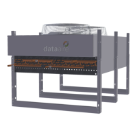
Data Aire air-cooled condensers (GHRC) provided with optional axial Electronically Commutated
(EC) fan(s) provide variable speed control based on head pressure. The EC motor has all the re-
quired components to run at variable speeds.
The control system in a GHRC condenser allows all fans to modulate, as required, to maintain the
proper head pressure of the unit.
4.6.1 EC Motor Speed Adjustments
The EC motor varies its speed linearly based on a 0-10V input signal from the head pressure trans-
ducers. The fans are scaled per the following table:
Refrigerant Pressure Settings (PSIG)
Refrigerant Cut-in 100
O
F Full Speed
R-410a 319 370
R-407c 226 270

 Loading...