Display User Manual
DDJ08001001 1-Mar-04
Page 5
2.3 Display Board Wiring
The Display face consists of 3 rows by 8 columns of GB8831UBR Display Boards. Each Board
consists of an 8 high x 8 wide pixel matrix of ultra-bright red LEDs with each pixel consisting of a
three LEDs. This results is an overall matrix of 24 high by 64 wide Display. The Boards are driven in
a multiplex mode with the row anodes connected to the horizontal drive and the column cathodes
connected to the vertical drive. The Boards contain the display driver circuitry, which generates the
multiplexing signals for illuminating the LEDs.
Data enters the Board from the Logic Board on a 14-way screened Horizontal ribbon cable via an
IDC socket.
The Display Boards are fixed to stand-offs attached to the Display chassis using 4 off M6 steel
screws.
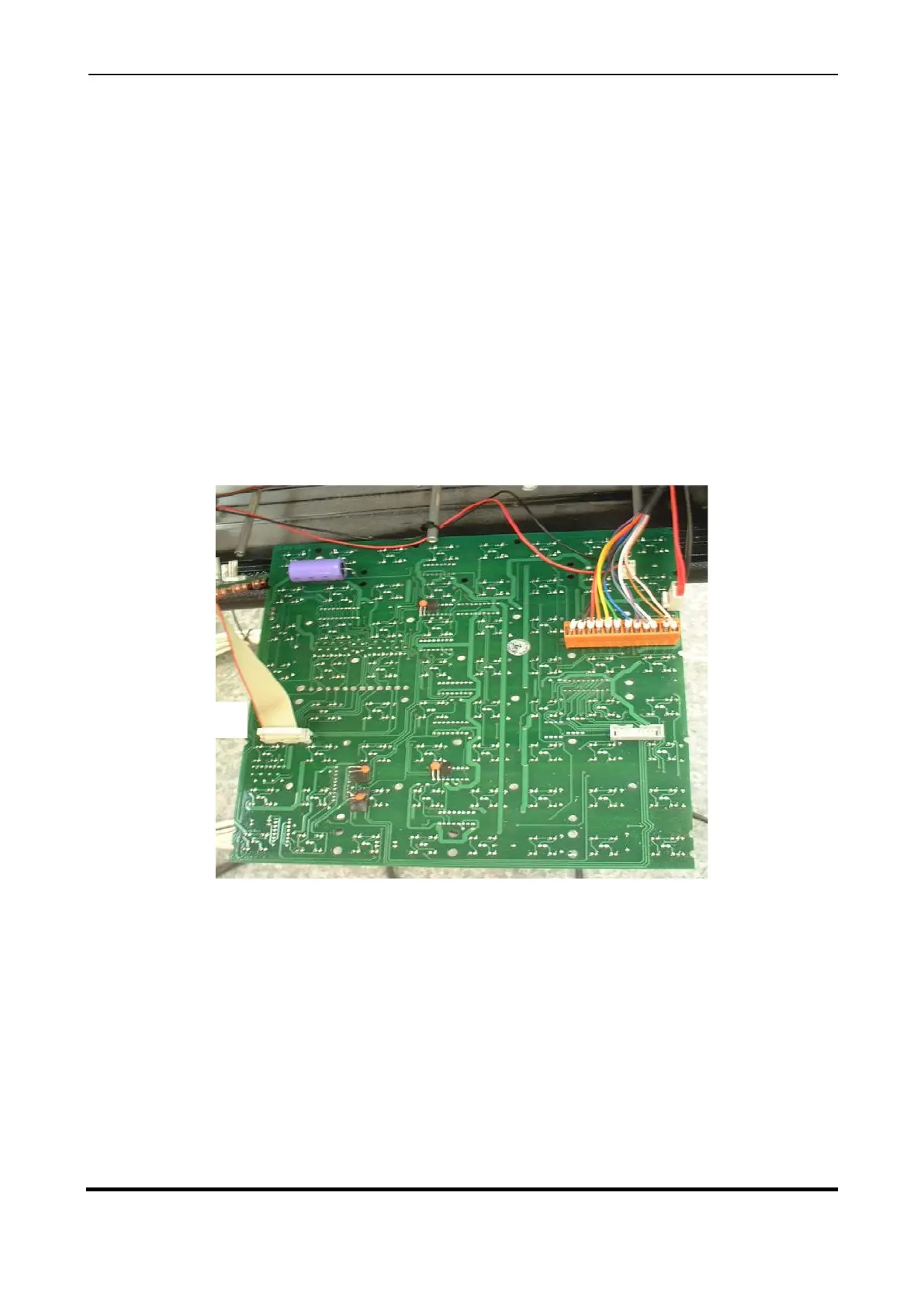
Figure 2.2 – Display Board Wiring.
Pin 2 - Gold
Pin 3 - White
Pin 4 - Grey
Pin 5 - Violet
Pin 6 - Blue
Pin 7 - Green
Pin 8 - Yellow
Pin 9 - Orange
Pin 10 - Red
Pin 11 - Brown
Ribbon Cable to
next Board
12 core cable from
Interface Board