Do you have a question about the Datakom DKG-317 and is the answer not in the manual?
Details the unit's functions including operation, protection, measurement capabilities, and connectivity options.
Describes the unit's function as a control and protection panel for gensets, highlighting user friendliness and programmable parameters.
Details the procedure for panel mounting, including dimensions and the use of retaining steel springs for secure installation.
Provides essential wiring instructions, including fuse recommendations and safety warnings for electrical connections.
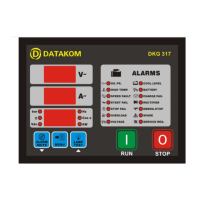
Details the 20 LEDs on the unit, categorized into Warning/Alarm group and Unit group, explaining their functions and indicators.
Explains the 3 seven-segment displays used for parameters, counters, and program settings, and navigation via the MENU button.
Details the capability for remote start via a signal to the SPARE-2 input, overriding password prompts and alarms.
Explains how to select oil pressure and temperature sender types, listing supported VDO and DATCON models.
Describes the SERVICE REQUEST LED for periodic maintenance, its function, and how to reset the service period.
Explains the non-erasable engine hour meter and how to display the total engine hours via the statistics menu.
Covers the connection of a modem for remote monitoring and programming over the telephone network, requiring parameter P_043.
Details remote monitoring and programming via RS-232 port, software download, and supported USB to serial adapters.
Configures Low Oil Pressure, High Temperature, and Coolant Level inputs, covering operation, monitoring, latching, contact type, switching, and response delay.
Configures Rectifier Fail, Emergency Stop, and Spare-1 inputs, covering operation, monitoring, latching, contact type, switching, and response delay.
Configures Spare-2 Fault Input and Program Lock Input, covering operation, monitoring, latching, contact type, switching, and response delay.
Defines the ohm-bar characteristics for the oil pressure sender using up to 6 points, with an example table provided.
Defines the ohm-degrees characteristics for the temperature sender using up to 6 points, with an example table provided.
| Brand | Datakom |
|---|---|
| Model | DKG-317 |
| Category | Remote Starter |
| Language | English |