Do you have a question about the Datakom DKG-116 and is the answer not in the manual?
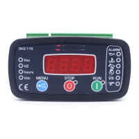
Explains manual control using RUN/STOP buttons and remote control via REMOTE START input signal.
Details engine cranking, running behavior, and shutdown sequence upon fault detection.
Describes menu button use for parameter scrolling, program mode entry, and lamp test.
Notes that total engine run hours are stored in tamper-proof memory.
Lists generator voltage (L1-N, L1-L2) and frequency measurements.
Indicates battery voltage is a measured parameter.
Details the auxiliary output feature, which is negative pulling.
Highlights manual/remote control, generator protection, and built-in alarms.
Includes True RMS measurements, tamper-proof hours display, and field adjustable parameters.
Details digital inputs (4), high current outputs, and auxiliary output.
Mentions surviving cranking dropouts, sealed front panel, and plug-in connection.
Emphasizes using correct circuit breakers, fuses, and disconnecting power before work.
Advises against touching terminals when running and using only dry cloths for cleaning.
States electrical equipment should be serviced by competent personnel and unit is for front panel mounting.
Requires High Temperature and Emergency Stop inputs to be connected to Battery negative.
Lists 8 programmable parameters including voltage limits, frequency, oil input, and phases.
Describes entering program mode via long-pressing MENU and navigating parameters.
Instructs to solder a wire to JP1 terminals for diesel engine control.
Details how to set the Low AC Voltage limit (U-Lo) using MENU, RUN, and STOP buttons.
Details how to set the High AC Voltage limit (U-HI) after saving the Low AC Voltage limit.
Describes setting Nominal Frequency (Fr9) and Oil Input type (OIL).
Details setting Fuel output type (FUEL) and Relay-3 function (rLY3).
Describes setting the Choke timer (CHOL) and Number of Phases (3-1P).
Explains how to exit program mode by pressing MENU for 3 seconds.
Illustrates the terminal connections for Battery, Starter Motor, Generator, and control signals.
Provides detailed electrical, environmental, and physical specifications of the unit.
Shows the required dimensions for mounting the unit into a panel.
Details the quantity per package and package dimensions/weight.
| Brand | Datakom |
|---|---|
| Model | DKG-116 |
| Category | Remote Starter |
| Language | English |