Do you have a question about the Datakom DKG-309 and is the answer not in the manual?
Covers mains failure, engine control, generator protection, and basic alarms.
Includes standby, load shedding, gas engine support, and idle speed control.
Features RS-232, modem/SMS, MODBUS, LCD display, and language selection.
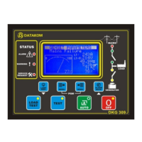
Overview of the genset control panel and its measured parameters.
Instructions for mounting the unit onto a panel, including grounding requirements.
Guidance on wiring connections, fuse recommendations, and electrical safety precautions.
Details on generator/mains contactor outputs and phase/neutral inputs.
Connection points for fuel, oil pressure, temperature sensors, and digital inputs.
Specifies connections for generator current transformer inputs.
Explains the meaning and operation of various LED indicators on the unit.
Details the graphical LCD display, including displayed information and navigation.
Defines alarm priorities, reaction, and latching behavior.
Details alarms for oil pressure, temperature, fuel level, and rectifier status.
Covers alarms related to frequency, voltage, battery, ECU, and phase order.
Operation for automatic mains and genset transfer.
Procedures for testing the genset operation with or without load.
Enables remote start, mains simulation, and engine heating operations.
Covers fuel pump, block heater, idle speed, dual genset, and exerciser functions.
Includes modem, SMS, MODBUS, remote monitoring, event logging, service, and reset.
Explains how to connect the unit via RS232, RS422/485, or modem.
Provides a list of readable Modbus registers for data access.
Defines programmable turn-on/turn-off time pairs for daily genset operation.
Details how events are stored, displayed, and navigated within the unit.
Lists incremental counters for engine hours, runs, and service intervals.
Advises on safe cleaning practices and cautions against opening the unit.
Instructions on entering and navigating the programming menu.
Settings for LCD contrast, language, default display, and timers.
Configuration for current transformers, voltage limits, and power settings.
Parameters for frequency, oil pressure, temperature, and engine heating.
Defines behavior for digital inputs like emergency stop and low fuel switch.
Assigns functions to programmable relay outputs.
Adjusts measurement calibration for voltages, currents, and power.
Addresses issues with incorrect AC voltage or frequency readings.
Troubleshoots failure to start or engine stopping issues.
Diagnoses wiring errors, parameter skips, and inoperative unit issues.
States compliance with low voltage and EMC directives.
Details voltage, frequency, current, input/output ratings, and communication port.
Covers operating temperature, humidity, dimensions, weight, and IP rating.
| DC Outputs | Fully configurable. |
|---|---|
| DC Input | Fully configurable. |
| Current Consumption | 100 mA DC typical |
| Operating Temperature | -20°C to +70°C |
| Maximum Humidity | 95% non-condensing |
| Current Consumption (Operating) | 100 mA DC typical |
| Communication | RS-232 |