BA300 - BA700
M12 PANEL CONNECTORS
INSTALLATION MANUAL
DESCRIPTION
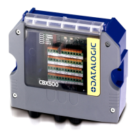
The BAxxx M12 Panel Connectors are accessories for the CBX series
connection boxes and SC4000 Controllers. They provide direct
connection between the box and the network using standard cables.
All the connectors come with IP65 protection caps so that in case of
temporary use, (i.e. Service connector for reader configuration), this
cap can be replaced to maintain IP65 protection when not connected.
NOTE
IP65 protection is provided when the BAxxx is
correctly mounted to the box and either the IP65
protection cap is in place or the cables are properly
mated.
Connector Description
BA300
Service
Connects to the Aux Port inside the CBX or
SC4000 to allow for software configuration through
an external PC without opening the box therefore
reducing maintenance time.
BA400
Ext. Power
Connects to the Vdc and GND terminals as Power
Input to the box.
BA500
Trigger
Connects to the Input 1 signals to allow connection
to the trigger (presence sensor).
BA600
ID-NET Out
Provides ID-NET and power signals towards the
next device in the network (power Out).
BA700
ID-NET In
Provides ID-NET and power signals from the
previous device in the network (power In).
821001631 (Rev. A)
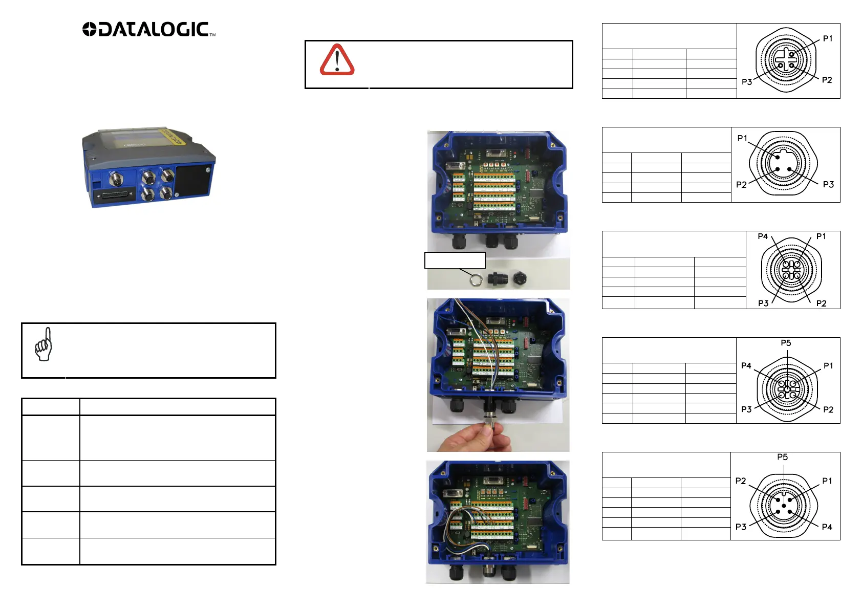
INSTALLATION
CAUTION
Power must be off during this operation.
The BAxxx Panel Connectors can easily be installed into the CBX series
or SC4000 by substituting any one of the compression connectors and
mounting the M12 Connector in its place.
1. Remove the compression
connector with its retaining
nut.
2. Insert the retaining nut of
the M12 connector.
3. Install the M12 connector
passing its wires through
the retaining nut. Tighten
the connector to between 2
and 2.5 Nm so that the
o-ring seals against the
CBX or SC4000 body.
4. Insert the wires into the
relative spring clamp
connectors according to the
pinout tables.
Using a device such as a
screwdriver, push down
on the lever directly
above the clamp.
Insert the wire into the
clamp and release the
lever.
BA300 (Service)
M12 3P Female (B-coded)
Pin Color Function
1 Brown RXA
2 White GND
3 Blue TXA
BA400 (Ext. Power)
M12 3P Male (B-coded)
Pin Color Function
1 Brown Earth
2 White Vdc
3 Blue GND
BA500 (Trigger)
M12 4P Female (A-coded)
Pin Color Function
1 Brown +V
2 White I1A/B
3 Blue -V
4 Black I1A/B
BA600 (ID-NET Out)
M12 5P Female (A-coded)
Pin Color Function
1 Brown Shield
2 White Vdc
3 Blue GND
4 Black ID+
5 Grey ID-
BA700 (ID-NET In)
M12 5P Male (A-coded)
Pin Color Function
1 Brown Shield
2 White Vdc
3 Blue GND
4 Black ID+
5 Grey ID-
Retaining Nut