CBX500 INSTALLATION MANUAL
8
POWER SUPPLY
Power is supplied to the CBX500 through the Vdc and GND pins provided on the spring
clamp connector.
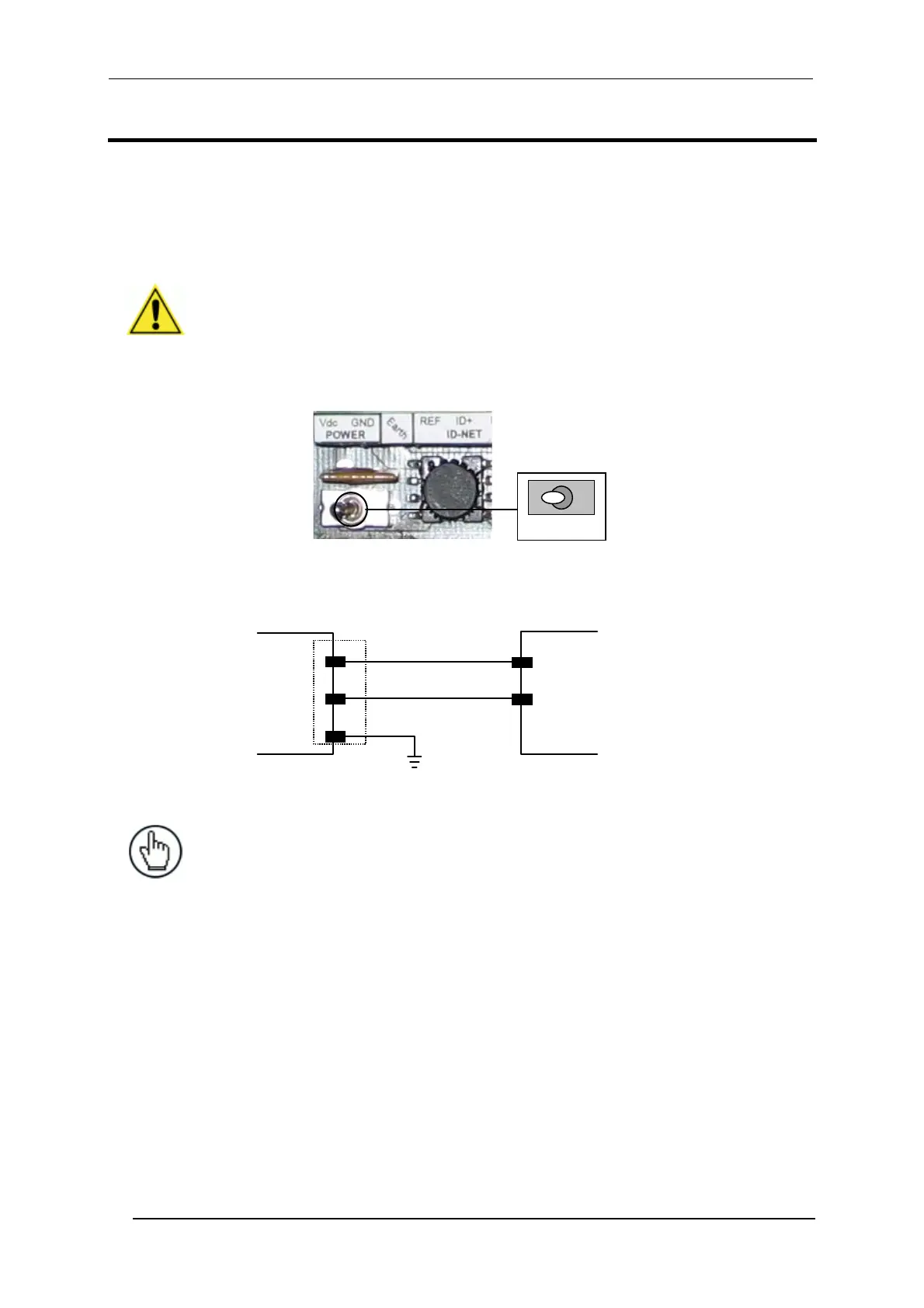
The power switch (see Figure 3) switches the power supply ON or OFF for both the CBX500
and the connected reading device.
CAUTION: The power switch does not control power to the Vdc/GND, +V/-V
spring clamps, therefore any devices connected to these signals (i.e. external
trigger, encoder, etc.), are live and are not protected from polarity inversion.
Disconnect the power supply when working inside the CBX500.
OFF
ON
Figure 3 - Power Switch ON/OFF Positions
CBX500
POWER SUPPLY
GND
GND
Vdc
V+ (10 - 30 Vdc)
Earth
Earth Ground
Figure 4 - Power Supply Connections
NOTE: Vdc is electrically connected to +V, just as GND is electrically
connected to -V. This is useful for supplying external trigger, inputs and
outputs from the CBX500 power source, however +V and -V signals should
not be used as power supply inputs to the CBX500.
The power supply must be between 10 and 30 Vdc only.