ACCESSORIES
Connection Description
Part
Number
Cables
BA300
Service
CAB-AUX03 M12 3P TO DB9
SERIAL CABLE 3M
93A051385
BA400
Ext. Power
CAB-PW-EXT M12 POWER
EXTENSION CABLE
93A051381
CBL-1480-01 M12/5P
MALE/FEMALE 1M IDNET
93A050049
BA600 / BA700
ID-NET Out / In
CBL-1480-02 M12/5P
MALE/FEMALE 2M IDNET
93A050050
Connectors
BA300 FMC300 M12 3P M. CONN.
SERVICE
93ACC1883
BA400 FMC400 M12 3P F. CONN.
POWER
93ACC1884
The FMC accessory connectors can be used to make custom External
Power and Service cables in case the standard cables don't satisfy the
application requirements.
GROUNDING
There are two general rules to follow regarding network grounding:
1) The network Shield must only be connected to Earth ground at
one point (the Master).
When using isolated power supplies, Earth grounding can be
accomplished through the CAB-PW-EXT accessory cable and the
BA400 connector.
Power Supply
Earth ground connection
BA400 on
Master
CAB-PW-EXT
2) All reader Chassis must be connected to Earth ground.
All the readers in the network must have their Chassis connected to
Earth ground either by: mounting to conductive metal brackets or
frames; or through the CBX or SC4000; or through the QL bushing.
In the case of grounding through the CBX or SC4000, connect the
Earth signal to a good earth ground and set the internal Chassis
jumper to Earth.
In the case of grounding through the QL bushing, connect a flying
lead from the mounting bushing to an Earth ground. The mounting
bushing is internally connected to the reader Chassis.
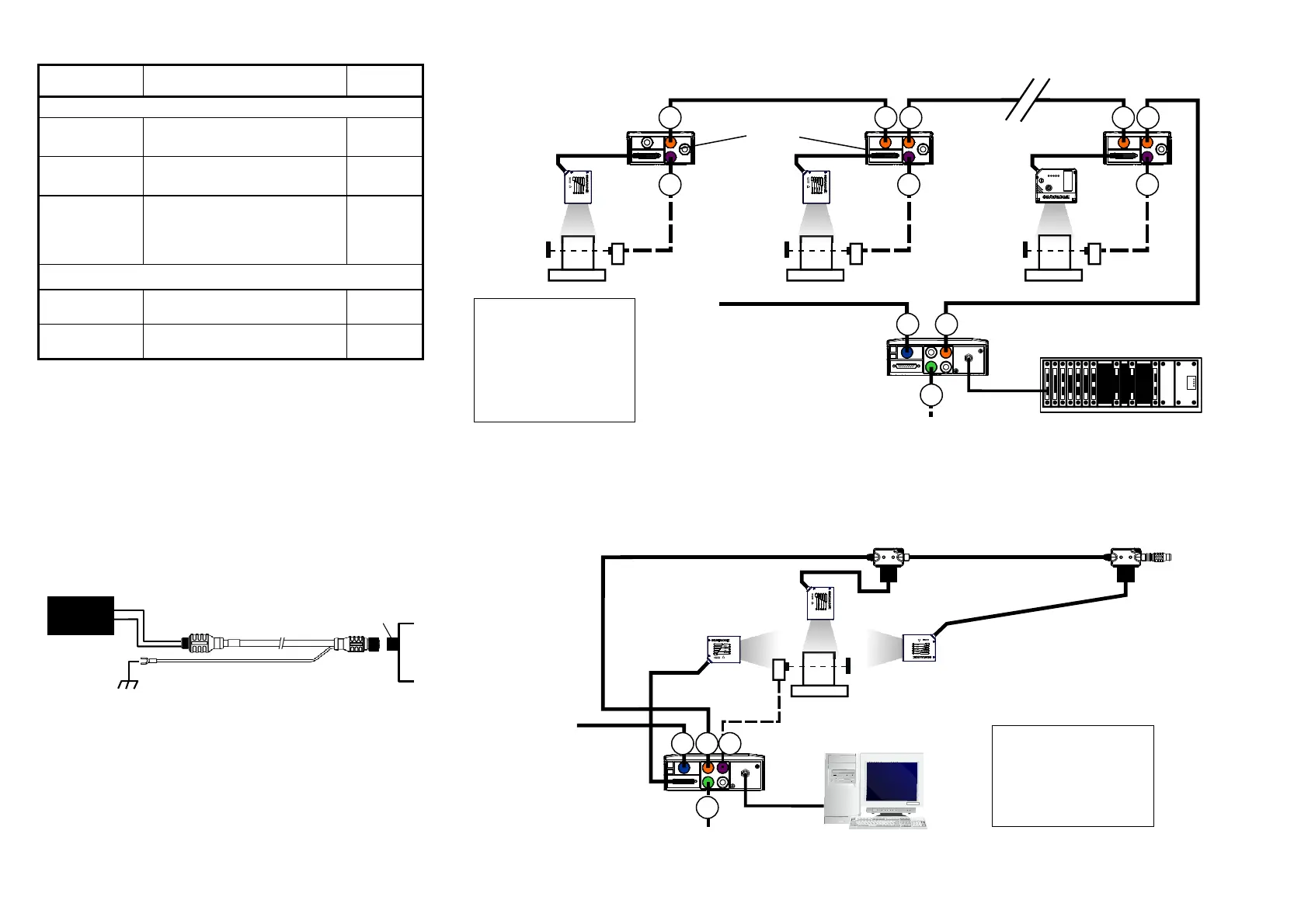
TYPICAL LAYOUTS
ID-NET™ Multidata Network - SC4000 Master + Scanner Slaves with CBX100
ID-NET™ Synchronized Network - Scanner Master with CBX500 / BM2x0 + Scanner Slaves with QL100
Power
ID-NET™ Slave Nodes
SC4000 Master
BA600 ID-NET™ Out
BA700 ID-NET™ In
BA400 Ext. Power
BA500 Trigger
BA300 Service
2 1
1
4
2
Host
PS PS PS
1 2
3
4 4
CBX100
The ID-NET network must be terminated
through the internal switch of the SC4000
and the last CBX in the network.
5
CBL-1480-xx
CBL-1480-xx
CBL-1480-xx
CAB-AUX03
Host
QL100
3 1 4
PS
Power
CBX500 w BM200
CBL-1490
ID-NET
Terminator
The ID-NET network must be terminated through the
internal switch of the CBX500 and inserting an ID-NET
terminator into the last QL in the network.
ID-NET™ Slave Nodes
5
CBL-1480-xx
CBL-1480-xx
CAB-PW-EXT
CAB-AUX03
CBL-1480-xx
BA600 ID-NET™ Out
BA400 Ext. Power
BA500 Trigger
BA300 Service
DS2100N
Master
QL100
Ethernet