EasyManua.ls Logo

Datalogic SR23 User Manual

Datalogic SR23
5 pages
To Next Page IconTo Next Page
Page #1 background imageLoading...
Page #1 background image
140
CATALOG | Photoelectric Sensors
SR
CATALOG
SECTION
APPLICATIONS
Processing and Packaging machinery
Automatic labelers
Multilayer labels detection
Up to 0,5 mm of minimum size labels/gap
5 mm slot width
50 mm slot depth
Dynamic or static setting through single push-button
12 kHz switching frequency
Compact and robust housing, IP65
M8 connector or 2 m cable models
PNP or NPN models
HIGH EFFICIENCY FORK
SENSOR FOR BOOKLET
AND MULTILAYER LABELS
DETECTION
SR23
SR23
Slot width
5 mm
Slot depth
50 mm
Switching frequency
12 kHz
Light emission
IR LED
Setting
push button
Power supply
Vdc 10…30 Vdc
Vac
Vac/dc
Output
PNP
NPN
NPN/PNP
relay
other
Connection
cable
connector
pig-tail
Approximate dimensions (mm)
30x63x10
Housing material
Alluminum (Zama), Plastic (PBT)
Mechanical protection
IP65
FORK SENSORS
Question and Answer IconNeed help?

Do you have a question about the Datalogic SR23 and is the answer not in the manual?

Datalogic SR23 Specifications

General IconGeneral
BrandDatalogic
ModelSR23
CategorySecurity Sensors
LanguageEnglish

Summary

Applications

Processing and Packaging Machinery

Applies to machinery used in processing and packaging operations.

Automatic Labelers

Suitable for use in automatic labeling machines and systems.

Technical Data

Power Supply and Ripple

Specifies input voltage range, reverse polarity protection, and ripple.

Output Characteristics

Details output type (PNP/NPN), current, and saturation voltage.

Performance Specifications

Covers switching frequency, response time, and slot dimensions.

Mechanical and Environmental Ratings

Includes housing material, protection rating, and operating temperatures.

Dimensions

M8 Connector Version Dimensions

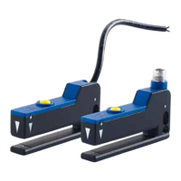
Provides detailed drawings and measurements for the M8 connector model.

Cable Version Dimensions

Illustrates dimensions for the sensor model with a cable connection.

Indicators and Settings

LED Indicators

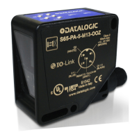
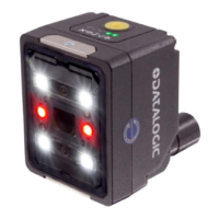
Explains the function of the yellow (output) and green (ready) LEDs.

Setting Push-button

Describes the role of the push-button for sensor configuration.

Connections

M8 Connector Wiring

Details the pinout and wiring for the M8 connector.

Cable Wiring

Outlines the color coding and connections for the sensor cable.

Model Selection and Order Information

Fork Sensor Models

Lists available fork sensor models with their respective output types and order numbers.

Cables

Axial M8 Connector Cables

Provides specifications for axial M8 connector cables, including type, length, and order number.

Radial M8 Connector Cables

Lists specifications for radial M8 connector cables, including type, length, and order number.

Controls

Output and Ready LEDs

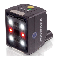
Describes the function of the yellow (output) and green (ready) indicator LEDs.

Set Push-button Functionality

Explains how to use the push-button for sensor acquisition and settings.

Setting Modes

Dynamic Acquisition

Guides on setting the sensor for dynamic label detection.

Static Acquisition

Details the procedure for static label detection setup.

Reversing Output Status

Instructions on how to invert the output signal logic.

Restoring Factory Settings

Procedure to reset the sensor to its original factory default configuration.

Output Short-Circuit Warning

Describes the indicator for output short-circuit conditions.

Remote Function and Push-Button Blocking

Remote Input Operation

Explains using the remote input wire for setting operations.

Earth Connection

Grounding Methods

Details the available methods for grounding the sensor unit.

Related product manuals