7
WARNING
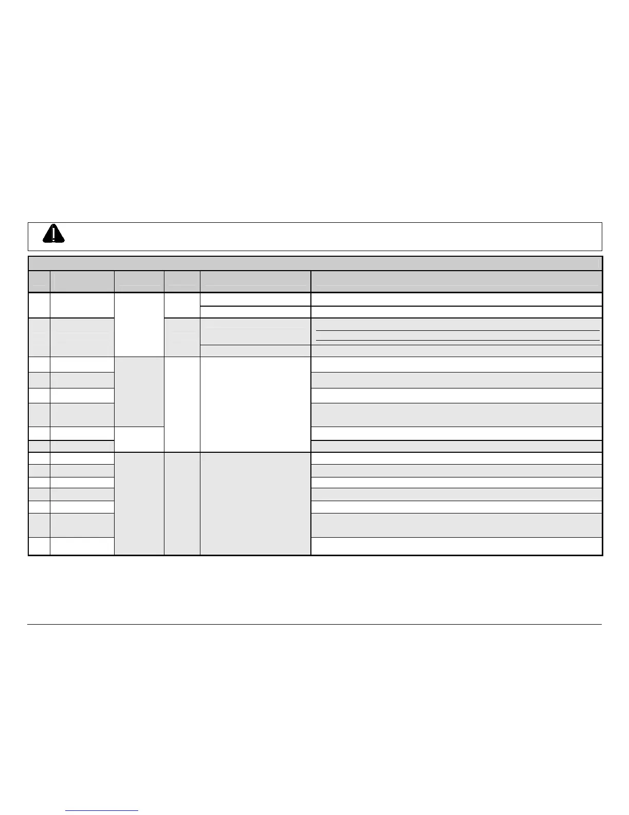
Failure to properly configure the GPIO Port can result in damage to the printer and / or connected devices.
GPI/O Port A Jumper Overview
Pin
Signal
Name
Direction
[1]
Jumper Position Function / Description
Installed Printer chassis is used.
1
Ground
JMP 3
Removed Ground must be supplied.
Installed
Printer +5VDC is used (.5 amp maximum)
Note: Drawing more than .5 amps can cause unreliable printer operation.
2 +5 VDC
N/A
JMP 2
Removed +5VDC must be supplied.
3 Start Of Print
[2]
Programmable
[3]
4 Slew Label
Media is advanced until the signal goes HIGH and, if not in continuous mode, the label
is positioned at the next available TOF.
5 Toggle / Pause The printer pauses when the signal is taken LOW.
6 Reprint
Input
The last label is reprinted exactly, with no increment or time stamp changes;
recommended for use during error conditions. Keeping this signal LOW produces non-
stop printing.
7 +24 VDC Printer +24 VDC (1.5 amp maximum).
8 Ground
N/A
N/A N/A
Printer chassis.
9 Ribbon Low Programmable
[1]
. Signifies a RIBBON LOW DIAMETER warning condition.
10 Service Required Evoked by occurrences listed under ‘Fault Messages.’
[1]
Active LOW.
11 End Of Print Programmable
[1]
. Signifies the End of Print (EOP) process.
12 Media Out Evoked during an Out of Stock condition. Active LOW.
13 Ribbon Out Evoked during an Out of Ribbon condition. Active LOW.
14 Data Ready
Evoked when a label is waiting to print. After Start of Print is received, printing will begin.
For synchronization with the print cycle, End Of Print indicates the completion of the
process. Active LOW.
15 Option Fault
Output JMP 1
When inactive, outputs will be
pulled up to a voltage
determined by this jumper
setting, where:
Pins 1 – 2 = +5VDC;
Pins 2 – 3 = +24VDC; or,
None = an external voltage
(not to exceed +30VDC) via
external pull-ups providing a
20K ohm feedback path
through any two outputs.
Evoked during a Linear Scanner or RFID fault condition. Active LOW.
[1]
Signal directions given relative to the printer.
[2]
If active with no current print job, “WAITING FOR DATA” will be displayed. Specifying a quantity of 9999 while keeping this signal ON will cause non-stop label printing, except
in single label “Imaging Mode”, which will cause the printer to stop between labels. See the Operator’s Manual for details.
[3]
For details see PRINTER OPTIONS / GPIO PORT in the Operator’s Manual.

 Loading...


