iPIO-2816_v180808n iPIO-2, iPIO-8, iPIO-16 Users Guide Page 4
4. Hardware Installation
4.1. Inputs and Outputs
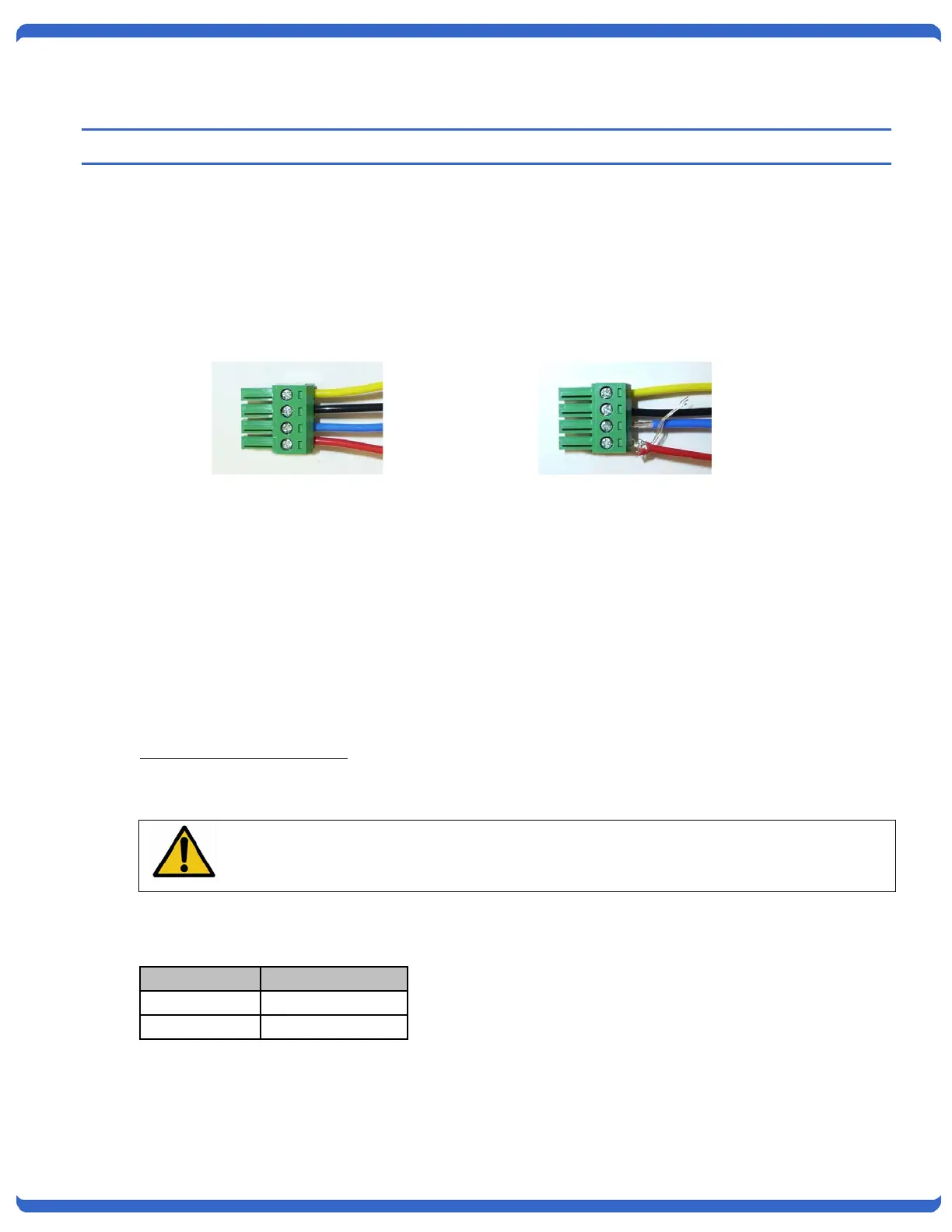
Connections to the iPIO Inputs and Outputs are made using screw terminal blocks. The screw terminal
blocks are on removable connectors for easy cable fabrication.
Make sure screw terminals are tightened securely and that there are no loose strands of cable or excessive
stripped wires.
4.2. Inputs
Connect the inputs to the iPIO using the screw terminals. Inputs can be either dry relay or switch contacts,
or a +VDC voltage (3 to 30 V), referenced to a common ground.
Screw terminals are removable for easy installation. Terminals for each circuit are marked + and G. When
connecting dry relay contacts, the polarity is not significant.
Connecting to +VDC Inputs
The iPIO is factory configured for dry contact closure inputs only. To configure for +VDC inputs, jumpers
must be removed.
Disconnect power and all cables prior to input configuration.
When connecting +VDC, connect the positive voltage to the terminal marked + and the negative or ground to
the terminal marked G.
Status DC Voltage
Open >3VDC
Closed <=0VDC
Connections.
Note Loose Wires and
Connections