BWS-T2 Series Instructions manual
16
3. ELECTRICAL CONNECTIONS
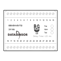
The BWS-T2 controller provides for the following connections:
Signal Terminal
Output 1 14; 29
Output 2 15; 30
Start 19; 20
Test 1 1;2
Test 2 3;4
Emitter 1 5;6;7;8
Receiver 1 21;22;23;24
Emitter 2 25;26;27;28
Receiver 2 9;10;11;12
Input +24 VDC 16
GND 18
Earth GND 17
See the individual diagrams (figures 10 - 13) for wiring details.
One (1) or two (2) emitter-receiver pair(s) can be connected to the BWS-T2.
If using only one Emitter-Receiver pair, the cables of the Emitter must be
connected to the EMITTER 1 terminals and the cables of the Receiver must
be connected to the RECEIVER 2 terminals.
The EMITTER 2 and RECEIVER 1 terminals remain free.
CAUTION
Supply only
the photocells from this device!
Always use shielded cables to wire the emitter and
receiver pairs.