BWS-T2 Series Instructions manual
20
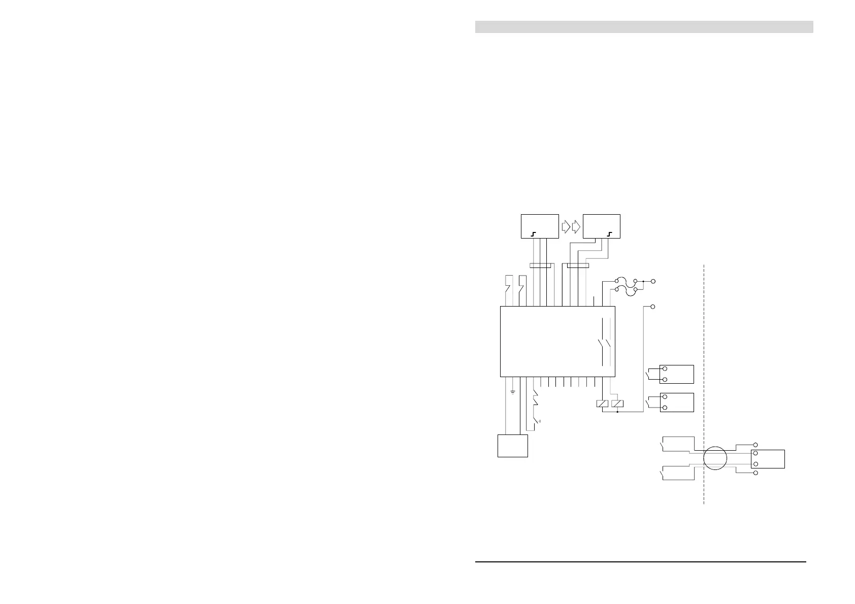
The maximum specified rating of the BWS-T2 output contacts must not be
exceeded.
With inductive loads, arc suppression or switching as described below
should be utilized. For user tools that require load currents that exceed the
BWS-T2 contact rating, auxiliary power operated switches must be used
(see figure 13).
The N.O. contacts of the auxiliary power operated switches H1/H2 are used
to wire directly to the machine control itself. The N.C. contacts of H1/H2
insure that in case of a defective switch the machine will not restart.
H1
H2
VOLTAGE
SUPPLY
24 V + 10 %
-
+
-
302928272617 18 19 20 21 23 24 252216
max. 220 VAC
FUSE
TEST1 TEST2
1512 3 4 567 8 9 10
11
1312 14
S
H
I
E
L
D
O
T
1
U
O
T
2
U
S5-5-G8-60
EMITTER
S5-5-F8-90
RECEIVER
START
POWER
OPERATED
SWITCHES
H1H2
L1
N
H2
H1
H2
CONTROL CABINET
H1
User tool
User tool
User tool
L1
N
SB-BW S-T2
+ - - +
Figure 13 - If load current exceeds Imax