Do you have a question about the Datex-Ohmeda S/5 Avance and is the answer not in the manual?
Information on the importance of proper training, tools, and understanding for servicing the equipment.
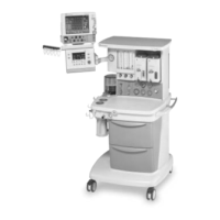
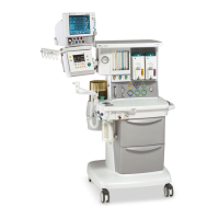
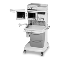
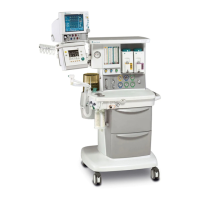
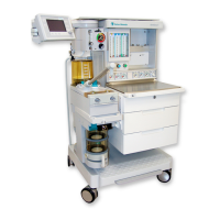
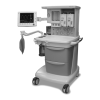
Overview of the components covered in the service manual for the S/5 Avance anesthesia machine.
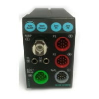
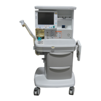
Identification of key front-view components of the anesthesia system.
Identification of key components within the breathing system of the anesthesia machine.
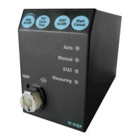
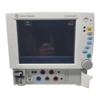
Explanation of the function of display controls like alarm silence, menu keys, and ComWheel.
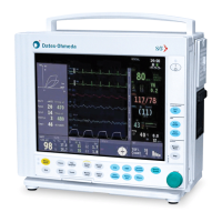
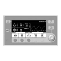
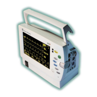
Description of the normal view of the anesthesia system display, showing various readouts.
Overview of the electrical system, including display and control boards and their functions.
Details on how mains power enters and is distributed throughout the system.
Information on the Anesthesia Control board's processor, memory, and communication interfaces.
Explanation of the Gas Mixer's pneumatic inputs, interfaces, and subassemblies.
Explanation of the three types of gas flow paths: ventilation, fresh gas, and scavenged.
Details on the pneumatic mechanical subsystems that constitute the ventilator.
Pre-testing checks to ensure the equipment is undamaged and correctly attached.
Procedures for performing system checks including leak, quick, vent, and O2 cell tests.
Procedure to test the vaporizer's back pressure, noting potential agent release.
Tests to verify the integrity and pressure of pipeline and cylinder gas supplies.
Testing various system alarms including O2, MV, Ppeak, PEEP, Apnea, and Leak alarms.
Tests to ensure electrical safety, including leakage current and ground resistance.
Overview of the service menu structure with three password-protected levels: Install/Service, Installation, and Service.
Accessing and using the super-user menu for system preferences and settings.
Accessing and using the installation menu for language, gas colors, hardware, and options.
Accessing and using the service menu for diagnostic tools and component tests.
Procedure to access and test primary regulators, with warnings about N2O and PCMCIA application.
Steps to adjust the drive gas regulator while maintaining a specific flow and pressure.
Overview of ventilator calibrations and the order in which they should be performed.
Detailed schedule for planned maintenance procedures, including parts replacement and checks.
Tests to verify the functionality and accuracy of the Electronic Gas Mixer.
Tests for integrated suction regulators, covering gauge accuracy, flow, regulation, and leak tests.
Procedure to test the capacity and health of the system's backup batteries.
A table outlining common problems, their possible causes, and recommended actions for troubleshooting.
Guidance on performing breathing system leak tests, including initial checks and flowchart references.
A detailed list of technical alarms, their conditions, priority, source, and troubleshooting actions.
Overview of the Avance Service Application, its loading, and main menu functions.
Procedures for performing gas diagnostics, including gas supplies, mixer output, and breathing system leak tests.
How to use the service application for ventilation diagnostics, including status, flow, and pressure readings.
Steps for diagnosing display issues, including testing LEDs, speaker, backlights, and keys.
Procedure for safely releasing gas pressure from the machine before disconnecting fittings.
Procedures for servicing the Display Unit, including removal, disassembly, and component replacement.
Procedures for servicing components within the lower electrical enclosure, such as boards and batteries.
Procedures for servicing components within the pan electrical enclosure, including the gas mixer and interface boards.
Instructions for removing and replacing components of the Vent Engine assembly.
Instructions for replacing cylinder supply modules, including primary regulators and inlet filters.
Procedure for replacing the Adjustable Pressure-Limiting (APL) valve.
Procedures for replacing components of the ABS breathing system, such as the Bag/Vent switch.
Procedure for changing the drive gas selection and ensuring proper system configuration and regulator function.
List of software tools and hardware adapters used for service and calibration.
Detailed part list for the Display Unit, including enclosure, boards, LCD, and connectors.
Part list for components located within the lower electronic enclosure, such as power and control boards.
Part list for components within the pan electrical enclosure, including the gas mixer and interface boards.
Illustrated parts and stock numbers for the Electronic Gas Mixer assembly.
Illustrated parts and stock numbers for the Vent Engine assembly and its subcomponents.
Illustrated parts and stock numbers for the O2 flush regulator and flush valve assembly.
Illustrated parts and stock numbers for the breathing system interface components.
A comprehensive schematic showing the overall system circuit connections and flow paths.
Detailed pneumatic circuit diagram showing gas flow paths and component connections.
Part 1 of a system block diagram showing major electrical and functional interconnections.
Part 2 of a system block diagram detailing connections for subsystems like the Vent Engine and gas mixer.
Electrical schematic for the AC Inlet module with 100-120 V supply, non-isolated outlets.
Electrical schematic for the AC Inlet module with 220-240 V supply and isolated outlets.
| Type | Anesthesia Workstation |
|---|---|
| Manufacturer | Datex-Ohmeda |
| Model | S/5 Avance |
| Display | Color touchscreen |
| Ventilator | Integrated |
| Ventilation Modes | Volume Control, Pressure Control, SIMV, Pressure Support |
| Gas Supply | O2, N2O, Air |
| Alarms | Configurable visual and audible alarms |
| Connectivity | Networked connectivity options |
| Power Supply | AC power, battery backup |
| Dimensions | Varies by configuration |
| Breathing System | Circle system with CO2 absorber |