EasyManua.ls Logo

Datex-Ohmeda S/5 Compact Anesthesia Monitor User Manual

Datex-Ohmeda S/5 Compact Anesthesia Monitor
72 pages
To Next Page IconTo Next Page
Page #1 background imageLoading...
Page #1 background image
Datex-Ohmeda
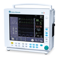
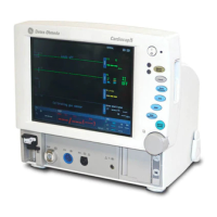
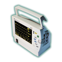
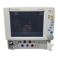
S/5™ Compact Anesthesia Monitor
S/5™ Compact Critical Care Monitor
Technical Reference Manual
All specifications are subject to change without notice.
CAUTION: U.S. Federal law restricts this device to sale by or on the order of a licensed medical
practitioner. Outside the USA, check local laws for any restriction that may apply.
Document No. M1019004
August 2004
Datex-Ohmeda, Inc.
P.O. Box 7550, Madison
WI 53707-7550, USA
Tel. 1-608-221-1551 Fax 1-608-222-9147
mailto:product.support.ussub@us.datex-ohmeda.com
www.us.datex-ohmeda.com
Datex-Ohmeda Division,
Instrumentarium Corp.
P.O. Box 900, FIN-00031
DATEX-OHMEDA, FINLAND
Tel. +358 10 394 11 Fax +358 9 146 3310
www.datex-ohmeda.com
2004 General Electric Company.
All rights reserved.

Table of Contents

Questions and Answers:

Datex-Ohmeda S/5 Compact Anesthesia Monitor Specifications

General IconGeneral
Display10.4 inch color LCD display
Parameters MonitoredECG, SpO2, NIBP, IBP, Temperature, Anesthetic Agents
Dimensions32 cm W
Power100-240 VAC, 50/60 Hz
Power SupplyInternal power supply with battery backup
ConnectivityRS-232, Ethernet

Summary

1 INTRODUCTION

Notes to the reader

Manual intended for service personnel and engineers, covering procedures for S/5 Compact Anesthesia and Critical Care Monitors.

Symbols

Explains symbols on transport packaging and equipment, including warnings and safety indicators.

Safety

Details safety precautions and warnings related to power connection, laser radiation, explosion hazards, and patient safety.

2 SYSTEM DESCRIPTION

Introduction

Overview of the S/5 Compact Monitor's modular, freely configurable system architecture for flexible parameter and feature sets.

Bus structure

Describes the two communication channels: CPU bus (ISA) for internal data transfer and module bus (RS-485) for parameter modules.

Parameter modules

Describes the general structure of parameter modules, including isolated and non-isolated sections for interfacing.

3 SYSTEM INSTALLATION

Unpacking instructions

Steps for confirming packing integrity, unpacking components, and checking for damage or missing items.

Choosing location

Factors to consider for selecting an installation location: lighting, space, connections, EMI, and environment.

Compact Monitor connections

Diagram illustrating various connection ports on the S/5 Compact Monitor, including network, serial, and optional WLAN.

Inserting the parameter modules

Guide on how to insert parameter modules into slots, noting restrictions on identical functions and listing module types.

Downloading Monitor Software

Instructions for downloading new monitor software via PCMCIA card, including steps and warnings about data loss.

Performing Factory Reset

Procedure to perform a factory reset via the Monitor Setup menu to restore default settings after software changes.

4 INTERFACING

Interfacing external monitors via the Interface Module, M-INT

Details on interfacing various external monitors (Datex-Ohmeda, Critikon, Abbott, Baxter, Nellcor) using the M-INT module.

Interfacing external bedside devices via S/5 Device Interfacing Solutions, N-DISxxx

Using N-DISxxx solutions to transfer data from external devices like ventilators and monitors to the S/5 system.

Interfacing printer

Guide to connecting compatible laser printers (serial or parallel) to the monitor's serial port.

Output Signals

Description of analog/digital output signals on connectors X4 and X8, including Defibrillation Sync and Nurse Call.

5 FUNCTIONAL CHECK

Recommended tools

List of necessary tools and their order numbers for performing functional checks on various monitor modules and options.

Visual inspection

Steps for performing a visual inspection of the monitor unit, connectors, and modules before functional testing.

Functional inspection

General procedures for functional inspection, covering monitor startup, fan operation, and initial module checks.

Compact Airway Module, M-CXXXXX

Check module operation, including fan, keys, spirometry flow, sample line blocking, and CO2 readings.

Hemodynamic Modules

Check temperature measurement functionality with a patient simulator, verifying displayed information.

NIBP module, M-NIBP

Check NIBP module keys, attach cuff, perform measurement, and verify cuff identification and result.

General

Perform electrical safety and leakage current tests, switch to standby, and complete final cleaning and documentation.

6 GENERAL TROUBLESHOOTING

APPENDICES A, B

Related product manuals