Installation 2-3
rect mating connector. To use other low-level audio accessories, the
correct mating connector can be obtained from DWC. The pin assign-
ments for the two connectors are as follows:
Accessory Connections
DWC has a variety of external accessories for use with the TW7000.
For some of these accessories and their control cabling, refer to the
Control Cabling Accessories figure on page 2-12. For more informa-
tion on any individual accessory, refer to the manual for that piece of
equipment.
Connector Pinouts
There are three accessory connectors on the back panel, each with dif-
ferent pin assignments. If multiple accessories are required that share
one or more of the accessory connectors, an external accessory com-
biner box (TW7000IOX) can be attached to any of these connectors.
All of the connectors on the back panel are a D-submini socket with 25
pins. For the location of these connectors, refer to the TW7000 Back
Panel figure on page 2-15.
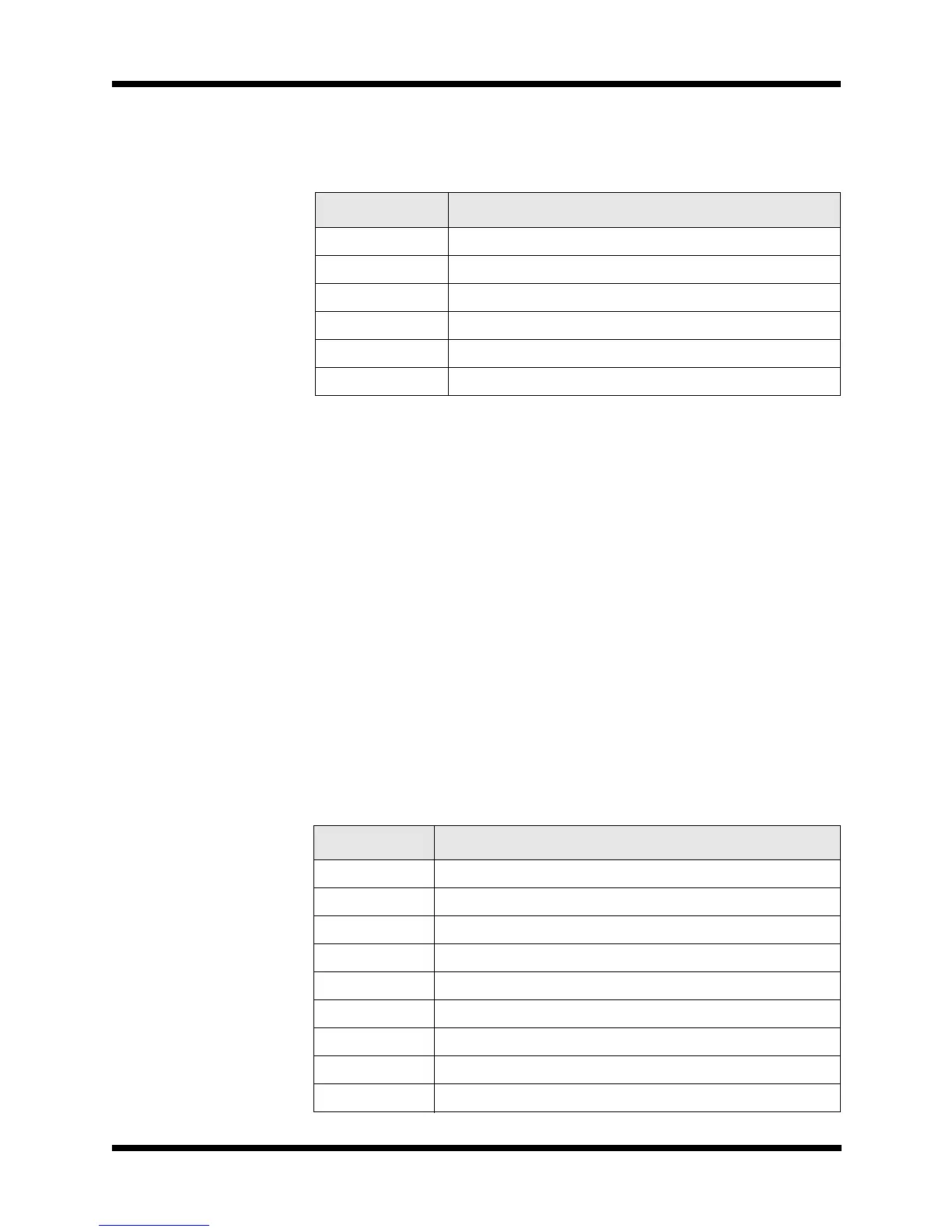
Pin Number Description
1 Ground
2 RX audio (unmuted)
3PTT
4 TX audio
5 CW key line
6 +12 Vdc
Table 2-1
Accessory Connector 1 Pinouts
Pin Number Description
1 Ground
2 COM1RXD (RX data)
3 COM1CTS (clear-to-send)
4 COM1TXD (TX data)
5 COM1RTS (ready-to-send)
6 BALRXA1 (balanced RX audio)
7 BALRXA2 (balanced RX audio)
8 BALTXA1 (balanced TX audio)
9 BALTXA2 (balanced TX audio)