4-2 Field Level Servicing
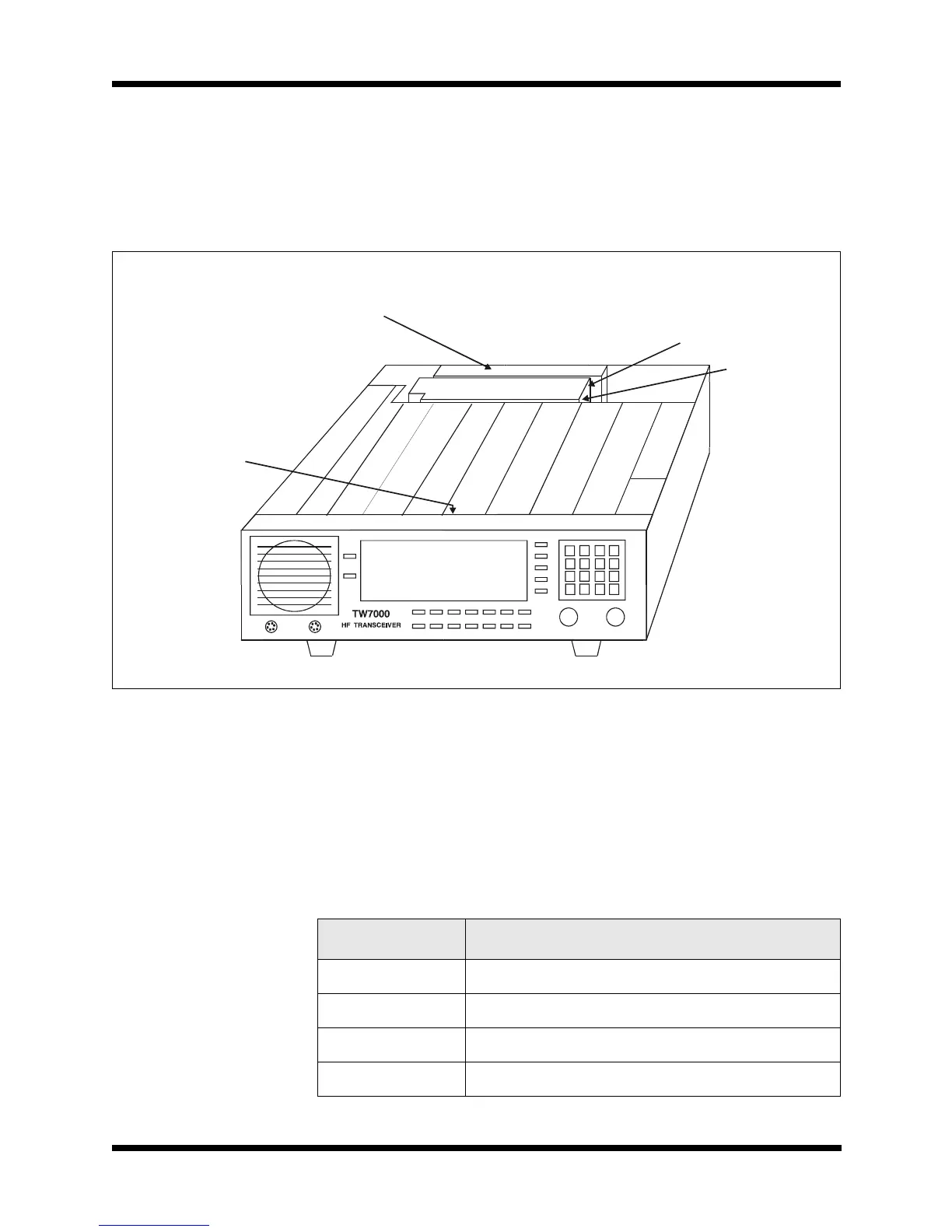
All boards, with the exception of the power amplifier, filter, and front
panel, are plug-in board assemblies and are easily accessible from the
top of the radio.
The front panel assembly is attached to the TW7000 with two screws
and a single-ribbon cable.
Field Level Servicing
The transceiver BITE system is designed to identify a faulty board.
Feedback is presented on the front panel display. In a matter of min-
utes, the radio can be opened up, the faulty board removed, and a new
one inserted. For detailed technical information, refer to the TW7000
technical manual (TW7000-MS).
Figure 4-1
Board Locations
A
L
E
F
S
K
/
I
S
D
N
O
P
T
2
O
P
T
1
R
e
f
C
o
n
t
r
o
l