12
7.8 Auto/Remote Control Centre with
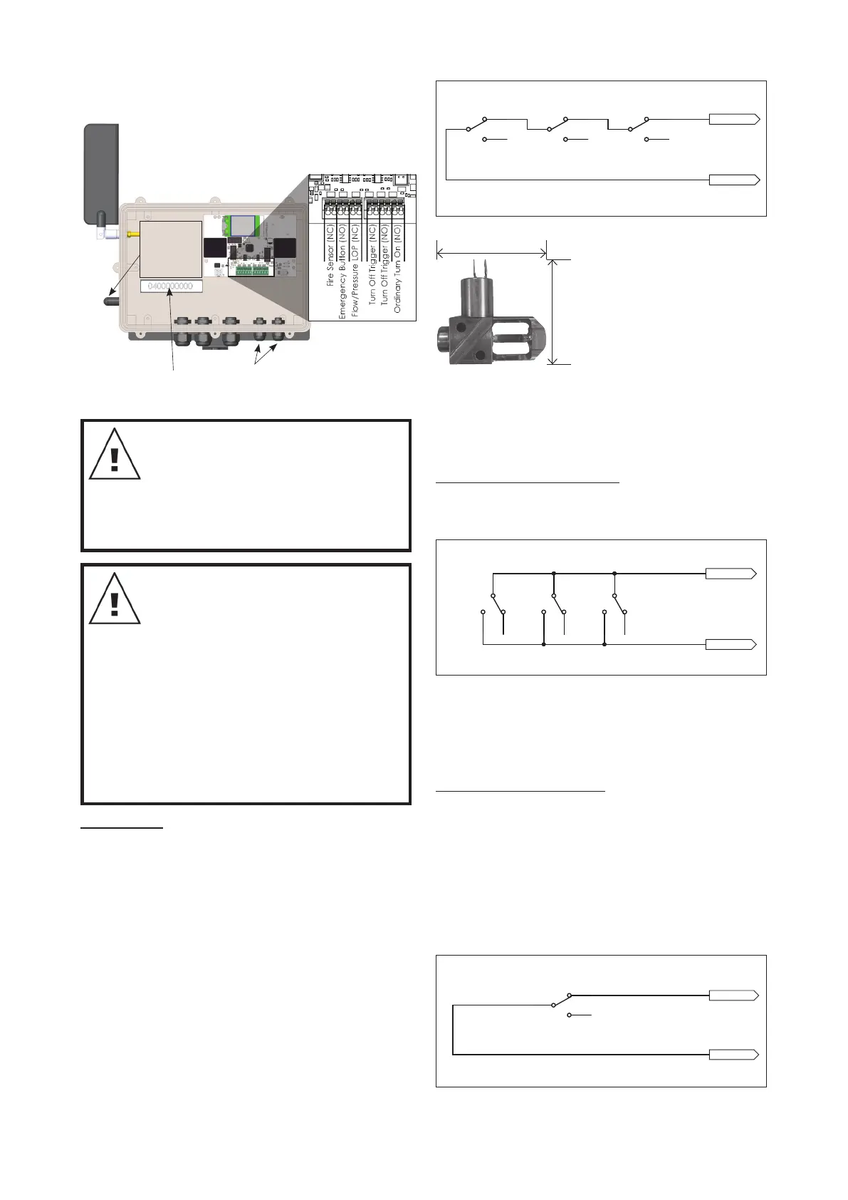
Cover Removed
Mobile Phone
Number
Access grommet
for re sensor/s or
external sensors
Speed Setting
Switch
UP = high speed
DOWN = low
speed
Figure 7.3
NOTE: To allow for automatic or
remote starting (e.g. by SMS) the
keystart must be left in the “ON”
position. Operation via SMS is only
possible where your pump Remote/
Auto Control Centre is within
reception range.
WARNING: Always disconnect battery
from engine prior to working on pump,
engine, or controller. Turning the key
start switch to “OFF” may allow a
remote start signal to enable engine
“cranking”, but not starting.
The black battery lead should be
connected to the negative terminal
(-ve) on the battery. Only once ready,
including after all necessary external
wiring connections are complete,
should the red lead be connected to the
positive terminal (+ve) on the battery.
Fire sensors: (Davey part number 402939). These
must be connected in series. The looped wiring is
connected to the Fire Sensor (NC) terminal and the
adjacent “GND“ terminal inside the Remote/Auto
Control Centre. The bridging wire included must be
removed if the re sensors are installed.
The wire used to connect the sensors should be
suitable for extra low voltage usage in the outside.
Wiring such as is used for automatic irrigation
control valves is ideally suited. Sizes 7/0.30 or
7/0.43 are more than sufcient for the purpose.
These should be protected from damage as an
open circuit (e.g. broken or cut wire) will result in
automatic pump start.
Sensors should be mounted on the edges of the
building or the property to be protected every 10
to 20 metres. The connecting wire must be in one
continuous loop.
2
3
1
2
3
1
2
3
1
Normally closed, stay on when open - only SMS can turn off
Fire Sensors
Input 1
GND 1
2
3
1
Normally open, stay on when closed - only SMS can turn off.
Emergency Button(s)
Input 2
GND 2
2
3
1
2
3
1
Normally open, turn on when closed,
off when open or Pressure or Float or LOP.
Ordinary Turn On Switch
Input 6
GND 6
2
3
1
2
3
1
At turn on, check closed within 4 minutes - otherwise LOP fault
Flow/Pressure LOP Switch
Input 3
GND 3
Once running, if opens fault after 30 seconds Bridge if not used.
Normally open, turn off when closed.
Float Turn-off
Input 5
GND 5
2
3
1
2
3
1
Normally closed, turn off when opened Bridge if not used.
Pressure Switch Turn-off (Tank or Shut-head)
Input 4
GND 4
Bridge if not used.
Normally open, run low speed when closed.
Speed Input
Input 7
GND 7
2
3
1
Figure 7.4
60mm
60mm
Figure 7.5
Once the pump is started via Fire Sensor it can only
be stopped via manual stopping (Turn the key to
“off”) or an SMS command to “stop” or the pump has
run out of fuel / oil alert shut down.
Emergency Switch or Button: These are used for
localised remote starting via a normally open push
button or switch. This is not an “on/off” switch, only
an “on” switch.
2
3
1
2
3
1
2
3
1
Normally closed, stay on when open - only SMS can turn off
Fire Sensors
Input 1
GND 1
2
3
1
Normally open, stay on when closed - only SMS can turn off.
Emergency Button(s)
Input 2
GND 2
2
3
1
2
3
1
Normally open, turn on when closed,
off when open or Pressure or Float or LOP.
Ordinary Turn On Switch
Input 6
GND 6
2
3
1
2
3
1
At turn on, check closed within 4 minutes - otherwise LOP fault
Flow/Pressure LOP Switch
Input 3
GND 3
Once running, if opens fault after 30 seconds Bridge if not used.
Normally open, turn off when closed.
Float Turn-off
Input 5
GND 5
2
3
1
2
3
1
Normally closed, turn off when opened Bridge if not used.
Pressure Switch Turn-off (Tank or Shut-head)
Input 4
GND 4
Bridge if not used.
Normally open, run low speed when closed.
Speed Input
Input 7
GND 7
2
3
1
Figure 7.6
Once the pump is started via Emergency Switch or
Button it can only be stopped via manual stopping
(Turn the key to “off”) or and SMS command to “stop”
or the pump has run out of fuel / oil alert shut down.
Flow/Pressure LOP Switch: This function allows for
a ow or pressure switch to be connected to detect
correct operation and shut down in the event of
closed head (ow switch option only) or loss of prime
(no ow or no pressure dependant on sensor used).
This option works best with a basic ow switch,
as the initiation time delay of 4 minutes is built in
allowing for a pump to gain prime (manual or SMS).
Once the pump is running LOP is also tied to a shut
down in the event of no ow after 30 seconds.
2
3
1
2
3
1
2
3
1
Normally closed, stay on when open - only SMS can turn off
Fire Sensors
Input 1
GND 1
2
3
1
Normally open, stay on when closed - only SMS can turn off.
Emergency Button(s)
Input 2
GND 2
2
3
1
2
3
1
Normally open, turn on when closed,
off when open or Pressure or Float or LOP.
Ordinary Turn On Switch
Input 6
GND 6
2
3
1
2
3
1
At turn on, check closed within 4 minutes - otherwise LOP fault
Flow/Pressure LOP Switch
Input 3
GND 3
Once running, if opens fault after 30 seconds Bridge if not used.
Normally open, turn off when closed.
Float Turn-off
Input 5
GND 5
2
3
1
2
3
1
Normally closed, turn off when opened Bridge if not used.
Pressure Switch Turn-off (Tank or Shut-head)
Input 4
GND 4
Bridge if not used.
Normally open, run low speed when closed.
Speed Input
Input 7
GND 7
2
3
1
Figure 7.7
 Loading...