EasyManua.ls Logo

Davey Monarch EcoSalt 20 - User Manual

Davey Monarch EcoSalt 20
16 pages
Print Icon
To Next Page IconTo Next Page
Loading...
email: sales@davey.com.au
web: davey.com.au
EcoSalt
Salt Water Pool Systems
INSTALLATION & OPERATING
INSTRUCTIONS
Includes Guarantee & Terms & Conditions
Model BMSC Series
IMPORTANT:
PLEASE READ THIS
DOCUMENT
CAREFULLY.
Please pass these
instructions on to the
operator of this
equipment.
Question and Answer IconNeed help?

Do you have a question about the Davey Monarch EcoSalt 20 and is the answer not in the manual?

Summary

Important Notice

Recommended Salt Levels

Guidelines for maintaining optimal salt levels for unit performance and cell longevity.

Chlorinator Cell Monitoring & Maintenance

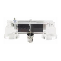
Procedures for monitoring and cleaning the electrolytic cell to prevent scale buildup and damage.

Installation Instructions

Installing the Power Supply

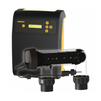
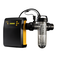
Location selection and mounting guidelines for the EcoSalt™ power supply unit.

Connecting the Electrolytic Cell

Cell to Power Supply Connection

Detailed steps for connecting the cell connectors and flow sensor to the power supply.

Operation of Your EcoSalt System

Understanding Cell Output Control

How the system controls cell output percentage and operates automatically.

Control Panel Overview

Red Operation LED Fault Diagnosis

Interpreting red LED warnings for common operational problems and solutions.

Safety Notice & Maintenance

Electrolytic Cell Maintenance

Factors affecting cell life and deposition on plates.

Day to Day Operation

Salt Level Requirements

Crucial information on maintaining the correct salt concentration for unit operation.

General Information

Recommended Pool Water Chemistry

Chart detailing ideal ranges and adjustment methods for pool water balance.

Troubleshooting

No Chlorine Production Issues

Checklist for diagnosing and resolving 'No Chlorine Production' problems.

Low Chlorine Production Issues

Checklist for diagnosing and resolving 'Low Chlorine Production' problems.

Overview

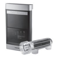
The EcoSalt™ Salt Water Pool System is a chlorinator designed for sanitizing swimming pools. It includes a power supply/controller and an electrolytic cell, along with barrel unions and reducing bushes for installation. The system operates by converting salt in the pool water into chlorine, providing a continuous supply of sanitizer.

Function Description

The EcoSalt™ system generates chlorine from salt dissolved in the pool water. The power supply/controller regulates the output of the electrolytic cell, which is where the electrolysis process takes place. The system features an electronic control and warning system to monitor operation and indicate potential faults.

Important Technical Specifications

  • Recommended Salt Level: 4500-6000ppm for standard pools; 2500ppm for above-ground pool models.
  • Calcium Hardness: 200-275ppm for concrete and tiled pools; 100-225ppm for other surfaces.
  • pH Levels: 7.4-7.6 for concrete and tiled pools; 7.2-7.4 for fiberglass pools.
  • Total Alkalinity: 80-150ppm.
  • Stabilizer (Cyanuric Acid): 30-50ppm (do not exceed 100ppm).
  • Chlorine Production (grams/hour at 100% output):
    • EcoSalt 13: 13 grams/hour
    • EcoSalt 20: 20 grams/hour
    • EcoSalt 26: 26 grams/hour
  • Maximum Pool Size (Litres):
    • EcoSalt 13: Cool Climates: 65,000; Temperate Climates: 40,000; Hot & Tropical Climates: 28,000
    • EcoSalt 20: Cool Climates: 100,000; Temperate Climates: 62,000; Hot & Tropical Climates: 44,000
    • EcoSalt 26: Cool Climates: 130,000; Temperate Climates: 81,000; Hot & Tropical Climates: 57,000
  • Power Supply Guarantee: 2 Years
  • Electrolytic Cell Guarantee: 3 Years (12 months for commercial/semi-commercial applications)

Usage Features

  • Installation: The power supply should be mounted vertically within one meter of filter equipment, 1.5 meters above ground level, and not within 3 meters of pool water. It must be kept away from acid, chemicals, and heat sources, with good ventilation. The cell should be fitted to allow for easy removal and cleaning, positioned after other accessories like heaters or pool cleaners, but before any division if there is more than one return line.
  • Pre-Start Up Procedure: Before operation, ensure the recommended salt level (4500-6000ppm or 2500ppm for above-ground pools) is achieved by adding salt to the pool and allowing it to mix thoroughly. Never add salt directly into the skimmer box. Initial chlorination with liquid or granular chlorine to reach 3ppm is recommended, and pool stabilizer (30-50ppm) must be added and maintained.
  • Control Panel Layout: Features a SANITISER OUTPUT DIAL (0-100%) to adjust chlorine production, POLARITY INDICATORS (A & B) to show cell polarity reversal, an OPERATION LED (Green for normal, Red for faults), a FUSE (3A), and a SELECTOR SWITCH for time clock settings.
  • System Control (Sanitiser Output Dial): This dial varies the duration the cell operates during the filtration cycle, not the electrical current. For example, at 80% setting during a 5-hour filtration cycle, the cell will operate for 4 hours. Setting to "0" turns the cell off.
  • Polarity Indicators A & B: These LEDs indicate the current polarity of the cell, which reverses over several hours or days to minimize scale buildup.
  • Low Salinity Indication: The Operation LED turns RED when salt levels fall below the minimum, indicating that salt needs to be added (25kg per 25,000 litres of pool water). Low salinity can damage the cell.
  • Automatic Time Clock Operation: The digital timer features a backlit Liquid Crystal Display (LCD) with 12-hour format. The SELECTOR SWITCH allows setting the current time, two ON/OFF timer sequences, and selecting Automatic ON, Manual ON, or OFF modes.
    • Set Clock (Position 1): Sets the current time.
    • Set Timer 1-ON (Position 2): Sets the start time for the first run sequence (factory pre-set to 6am).
    • Set Timer 1-OFF (Position 3): Sets the completion time for the first run sequence (factory pre-set to 8am).
    • Set Timer 2-ON (Position 4): Sets the start time for the second run sequence (factory pre-set to 5pm).
    • Set Timer 2-OFF (Position 5): Sets the completion time for the second run sequence (factory pre-set to 11pm).
    • Automatic ON (Position 6): Filtration system switches on and off automatically according to set times.
    • Manual ON (Position 7): Overrides automatic settings, keeping the filtration system ON constantly. Caution: Over-chlorination may occur.
    • OFF (Position 8): Switches filtration and sanitization OFF. Not recommended for long durations.
  • Running Times: During summer, run the chlorinator approximately 8 hours per day (preferably in two periods: 6-8 am and 5-11 pm). In winter, 4-6 hours per day is sufficient. In extremely hot weather or with heavy bathing loads, running time may need to be extended to 10-14 hours. Always run the filter when swimming.
  • Safety Devices: Includes a Gas Sensor that switches off chlorination if gas is detected or if there is no water flow. A Thermal Cut-Out prevents overheating.

Maintenance Features

  • Power Supply Maintenance: Little maintenance is required, except for replacing blown fuses. Periodically spray the wall or post (not the unit itself) with insect repellent to prevent insect penetration, which can damage electronics. The back of the unit is designed as a heat sink and may become hot.
  • Electrolytic Cell Maintenance: Regular monitoring and cleaning of the cell are essential to prolong its life and maintain efficiency. Calcium scale naturally builds up on the titanium plates during chlorination.
    • Cleaning Frequency: Inspect the cell at least weekly initially to determine the necessary cleaning cycle. Reverse polarity models minimize scale buildup, but manual cleaning may still be required in hard water areas.
    • Cleaning Procedure (Method 1): Mix 1 part Hydrochloric Acid to 10 parts Water in a suitable container. Pour the solution safely into the upturned cell or immerse the cell completely. Exercise extreme caution, using eye protection, a mask, and gloves.
    • Cleaning Procedure (Method 2): An approved commercial cell cleaning solution can be used.
    • Post-Cleaning: Rinse the cell thoroughly, dry connections, and return it to its position in the pipework. Cleaning should not take longer than a few minutes.
  • Water Chemistry Maintenance:
    • Salt Levels: Maintain 4500-6000ppm (2500ppm for above-ground pools). Low salt levels will damage the cell and void the warranty.
    • Stabilizer: Maintain 30-50ppm to reduce chlorine dissipation from sunlight.
    • pH and Total Alkalinity: Maintain correct pH (7.2-7.6) and Total Alkalinity (80-150ppm) to prevent problems like black spot, staining, cloudy water, and equipment damage.
    • Calcium Hardness: Maintain 200-275ppm (concrete/tiled) or 100-225ppm (other surfaces) to prevent excessive scale buildup.
    • Testing: Test pool water weekly for Free Chlorine, pH, Total Alkalinity, Calcium Hardness, and Stabilizer. Test salt levels regularly.
  • Cell Replacement: Insist on genuine EcoSalt replacement cells (MO681REP for EcoSalt 13, MO682REP for EcoSalt 20, MO683REP for EcoSalt 26). Using copy electrodes can seriously damage the unit's electronics and void the warranty.

Davey Monarch EcoSalt 20 Specifications

General IconGeneral
ModelEcoSalt 20
TypeSalt Chlorinator
Pool VolumeUp to 80, 000 liters
Salt Level4000-6000 ppm
Chlorine Output20 grams/hour
Voltage220-240V
Cell TypeSelf Cleaning
Warranty3 years

Related product manuals