EasyManua.ls Logo

Davey ChloroMatic MCS36C - User Manual

Davey ChloroMatic MCS36C
20 pages
Print Icon
To Next Page IconTo Next Page
Loading...
Salt Water Pool System
ESC Self Cleaning ESR Self Regulating
MCS16C MC16C
MCS24C MC20C
MCS36C MC30C
MCS40C
MC16CT
(12 Volt Light Output included)
MCS50C
MC20CT
(12 Volt Light Output included)
MCS16CT
(12 Volt Light Output included)
MCS24CT
(12 Volt Light Output included)
Installation &
Operating Instructions
ChloroMatic
®
Please pass these instructions on to the operator of this equipment.
Optional pH Pump
Question and Answer IconNeed help?

Do you have a question about the Davey ChloroMatic MCS36C and is the answer not in the manual?

Summary

IMPORTANT NOTICE

MAINTAIN OPTIMUM SALT LEVELS

Key factor for chlorinator performance and lifespan. Essential for optimal output.

MONITOR & MAINTAIN CHLORINATOR CELL

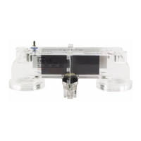
Regular monitoring and cleaning of the electrolytic cell prevents scale buildup and damage.

BALANCED POOL WATER CHEMISTRY

Maintaining correct pH, alkalinity, and hardness prevents equipment damage and ensures efficacy.

INSTALLATION INSTRUCTIONS FOR CHLOROMATIC

INSTALLING THE POWER SUPPLY UNIT

Guidelines for selecting a suitable, safe, and ventilated location for the power supply unit.

CONNECTING THE ELECTROLYTIC CELL

Details on correctly and securely connecting the flexible lead with brass connectors to the cell.

PRE-START UP PROCEDURE

POOL SALT ADDITION AND MIXING

Procedure for adding salt to the pool to achieve optimal levels for the chlorinator.

MINERAL SALTS USAGE GUIDELINES

Information on using mineral salts and their effect on chlorine production output.

INITIAL CHLORINE BOOSTING

Procedure for initially chlorinating a new pool to reach the target 3 ppm level.

STABILISER LEVEL MAINTENANCE

Importance of stabiliser for chlorine retention and recommended levels.

OPERATION OF YOUR CHLOROMATIC SYSTEM

CONTROL PANEL LAYOUT AND INDICATORS

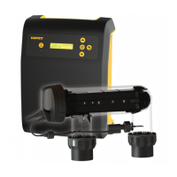
Overview of the control panel, including operation LEDs and display indicators.

CHLOROMATIC SERIES FEATURES AND OPERATION

ESR, ESC, ESCpH Series Key Features

Details on Stand-by, Flow, Sanitiser Output Control, and Low Salinity Indicator functions.

ESC System Specific Operational Features

Highlights Polarity Indicator, Sanitiser Output flashing, Electronic Cell Cleaning, and Pump Cut-out.

OPERATIONAL MODES AND TIMERS

WINTER MODE OPERATION GUIDELINES

How to use Winter Mode to adapt to cold water temperatures and alter low salinity detection.

DIGITAL AUTOMATIC TIME CLOCK SETUP

Setting and functions of the digital timer for automatic pool filtration cycles.

POWER SUPPLY AND ACCESSORIES

ANALOGUE TIME CLOCK OPERATION

Setting operating times using pins on the analogue timer for filtration cycles.

OPTIONAL POOL LIGHT TRANSFORMER CONNECTION

How to connect an optional pool light transformer to the unit.

POWER SUPPLY MAINTENANCE AND SAFETY

Fuse replacement, insect repellent application, and heat sink safety notice.

MAINTENANCE OF ELECTROLYTIC CELL

CELL DEPOSIT BUILD-UP FACTORS

Factors influencing scale buildup on cell plates and the need for regular inspection.

CELL REPLACEMENT GUIDELINES

Information on genuine replacement cell codes for ESR and ESC models.

ELECTROLYTIC CELL CLEANING PROCEDURES

Step-by-step instructions for cleaning MCS50C and 16-40g cells.

DAY-TO-DAY POOL CARE AND OPERATION

STABILISER IMPORTANCE AND LEVELS

Essential role of stabiliser in retaining chlorine and recommended levels.

OPTIMUM pH AND TOTAL ALKALINITY

Maintaining correct pH and TA levels for pool health and equipment protection.

CORRECT SALT LEVELS FOR OPERATION

Importance of maintaining recommended salt levels to prevent cell damage and warranty void.

RECOMMENDED RUNNING TIMES

Guidance on daily running times for optimal chlorinator performance and cell life.

CHLORINE PRODUCTION AND USAGE

OPTIMAL DAILY RUNNING TIMES AND TESTING

Recommended daily running times for summer and winter for sufficient chlorine generation.

SHOCK TREATMENT PROCEDURE

How to boost chlorine levels during extreme conditions using additional chlorine or extended run times.

CHLORINE TYPES AND MAX POOL SIZE COMPARISON

Comparison table of chlorine types and corresponding maximum pool sizes for different climates.

SAFETY DEVICES: GAS SENSOR AND THERMAL CUT-OUT

Explanation of built-in safety features protecting the unit and user.

GENERAL POOL WATER CHEMISTRY GUIDELINES

RECOMMENDED POOL WATER CHEMISTRY CHART

Table detailing ideal readings for free chlorine, pH, TA, calcium hardness, and salt.

COMMON POOL WATER TERMINOLOGY

Definitions of common terms related to pool water and sanitisation, like Algae, Bacteria, Chloramines.

IMPORTANT NOTES AND TROUBLESHOOTING

CRITICAL OPERATIONAL NOTES

Important reminders regarding guarantee, genuine parts, and potential damage from incorrect use.

TROUBLESHOOTING: NO CHLORINE PRODUCTION

Checklist of common causes and checks for the absence of chlorine production.

TROUBLESHOOTING: LOW CHLORINE PRODUCTION

Checklist of common causes and checks for reduced chlorine production.

CHLOROMATIC ESC WITH OPTIONAL PH SYSTEM

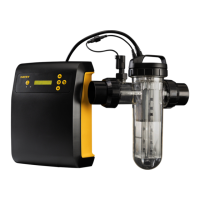
Overview of the ESC system with pH monitoring and auto-dosing capabilities.

INSTALLING AND MAINTAINING THE PH DOSING SYSTEM

INSTALLING THE PH PERISTALTIC PUMP MODULE

Reference to separate instructions for installing the pH pump module.

DILUTING POOL ACID FOR DOSING

Table and instructions for correctly diluting hydrochloric acid for the pH system.

ACID DOSING FITTINGS AND ATTACHMENTS

Guidance on connecting the acid container, tubes, and fittings to the pump and pool.

SENSORS, PUMP MODULE, AND ROLLER MAINTENANCE

Recommended maintenance schedule for pump tube, roller holder, and sensor probe.

ESC PH SYSTEM CONNECTION DETAILS

CHLOROMATIC CONTROLLER BASE CONNECTIONS

Identification of sockets on the controller base for pool pump and pH dosing pump.

ESC PH SYSTEM PLUMBING AND WIRING DIAGRAM

Diagram illustrating the correct plumbing and electrical connection of the ESC pH system.

DAVEY REPAIR OR REPLACEMENT GUARANTEE

WARRANTY PERIODS AND COVERAGE

Details on guarantee periods for different components and what is covered.

CLAIMS PROCEDURE AND EXCLUSIONS

How to make a claim, required proof of purchase, and common warranty exclusions.

MOUNTING TEMPLATE INFORMATION

MOUNTING TEMPLATE SPECIFICATIONS

Diagram showing dimensions for mounting the unit, specifically the 66mm spacing.

Overview

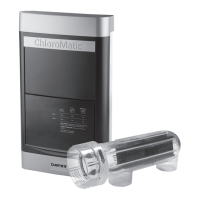
The Davey ChloroMatic Salt Water Pool System is a chlorinator designed for sanitizing swimming pools using salt water. It comes in two main series: ESC Self Cleaning and ESR Self Regulating, with various models within each series (e.g., MCS16C, MCS24C, MC16C, MC20C). Some models, like the MCS16CT and MCS24CT, include a 12 Volt Light Output. The system is also suitable for use with mineral salt pools.

Function Description:

The ChloroMatic system generates chlorine from salt water to sanitize the pool. It features an electronic control and warning system that regulates output and indicates potential faults or damaging operating conditions. The Cell Output is displayed as a percentage, fluctuating around 100% during normal chlorine production, or around 85% in Winter Mode.

Key Features:

  • Sanitiser Output Control: This dial varies the amount of time the electrolytic cell operates during the filtration cycle, from MIN (OFF) to MAX (ON). It adjusts in 10% steps.
  • Automatic Time Clock Operation: The system can be fitted with either a digital or analogue timer. The digital timer allows setting of two ON/OFF time sequences for automatic filtration system operation. The analogue timer has small pins for setting operating times, with a pre-set of 8 hours per day.
  • Winter Mode: This feature is activated when pool water temperature drops, altering the Low Salinity Indicator setting and reducing cell output by approximately 15%. It's designed for cold pool environments and should not be used during swimming season.
  • Low Salinity Indicator: This system uses operation LEDs to indicate when salt levels in the pool are low, which can increase wear on the cell. A red LED indicates that salt levels should be increased.
  • Gas Sensor: Incorporated into the unit and cell, this safety device switches off chlorination if gas is detected in the cell housing or if there is no water flow.
  • Thermal Cut-out: Prevents overheating by automatically disconnecting power if the temperature rises too high, resuming operation when it cools down.
  • Optional Pool Light Transformer: Some models can be fitted with a pool light transformer (Max power: 150W at 12VAC).
  • Optional pH Dosing System (ESCpH models): This combination unit includes a pH monitoring, auto-dosing peristaltic pump that feeds diluted acid into the pool to reduce pH levels. It operates during the preset filtration timer cycles of the chlorinator.

Specific Features of ESC Self Cleaning System:

  • Polarity Indicator on Output Display: A ± symbol appears before the cell output display to indicate the current polarity (positive or negative), which alternates and is factory pre-set.
  • Sanitiser Output Display: When adjusting the Sanitiser Output, the Cell Output Display flashes the control setting for a few seconds before resuming the Cell Output display or standby light.
  • Cleaning of Cell: Utilizes a patented Electronic reverse polarity system to clean the cell, minimizing maintenance.
  • Pump Cut-Out: A protective interlock system cuts off power to the pool pump if there is no water flowing through the cell housing, preventing the pump motor from burning out.

Important Technical Specifications:

  • Optimum Salt Levels: 4500-6000ppm. Operating at low salt levels will damage the cell and reduce its life.
  • Calcium Hardness: 200-275ppm for Concrete and Tiled Pools; 100-225ppm for other surfaces.
  • pH Levels: 7.2-7.4 for Fibreglass; 7.4-7.6 for Concrete & Tiled.
  • Total Alkalinity: Ideal range 80-150 ppm.
  • Stabiliser (Cyanuric Acid): 30-50 ppm, not to exceed 100 ppm.
  • Chlorine Production: The unit expresses production as pure 100% chlorine. When using mineral salts exclusively, chlorine production is 50% of the normal rated output.
  • Power Supply Installation: Must be mounted vertically, 1.5 meters above ground level, within one meter of filtration equipment, and not within 3 meters of pool water.

Usage Features:

  • Pre-Start Up Procedure: Requires loading salt into the pool (45-60kg per 10,000 litres for all models) and ensuring complete dispersal. For new pools, add sufficient chlorine (liquid or granular) to achieve 3 ppm or run the chlorinator continuously for at least 24 hours. Stabiliser must be added and maintained.
  • Running Times: During summer, the chlorinator should run approximately eight hours per day (preferably in two periods: 6-8 am and 5-11 pm). In winter, 4-6 hours per day is recommended. Running the chlorinator for 24 hours a day or for long periods will greatly reduce cell life.
  • "Shock" Treatment: Periodically, especially in hot conditions, the amount of chlorine can be boosted by adding liquid or granulated chlorine, or by extending running time.
  • pH Dosing System (ESCpH): Automatically doses diluted acid to maintain pH levels. The pH probe must be located before a heater or an electrolyser.

Maintenance Features:

  • Electrolytic Cell Maintenance: Regular inspection and cleaning of the cell are essential to prevent calcium scale build-up, which can reduce efficiency and lifespan. Reverse polarity models minimize scale build-up but may require occasional manual cleaning in hard water areas or when using mineral salts.
  • Cell Cleaning:
    • MCS50C Cell: Disconnect from power supply and pool return line. Place inverted in a tub/bucket. Pour cleansing fluid into the cell, ensuring plates are fully submersed. Examine after a few minutes and repeat if necessary. Rinse with clean water and refit.
    • 16-40g Cell: Turn off chlorinator, remove leads, unscrew cell from housing. Immerse cell in a solution of 1 part Hydrochloric Acid to 10 parts WATER for a few minutes. Alternatively, use an approved commercial cell cleaning solution. Never use concentrated acid, leave the cell in solution for extended periods, or use metal implements/scourers/brushes.
  • Power Supply Maintenance: Little maintenance is required, except for replacing blown fuses. Periodically spray the wall/post (not the unit itself) with insect repellent to prevent insect damage.
  • pH Peristaltic Pump Module Maintenance (ESCpH): The "squeeze" tube in the peristaltic pump is perishable and should be replaced approximately once per year. The roller holder should be inspected and replaced every 2 years. Ensure the sensor probe remains moist to prevent damage.
  • Water Chemistry Monitoring: Regularly test salt levels, pH, total alkalinity, calcium hardness, and stabiliser levels. Refer to the recommended pool water chemistry chart for ideal ranges.

Warranty Information:

  • Power Supply: Three Years
  • Electrolytic Cell: Three Years
  • pH Pump Module: One Year
  • Sensor Probe: One Year The guarantee does not cover commercial or semi-commercial installations running more than an average of 8 hours per day (12 months warranty for these). Using copy electrodes or not maintaining optimum salt levels will void the warranty.

Davey ChloroMatic MCS36C Specifications

General IconGeneral
Cell MaterialTitanium
TypeSalt Chlorinator
Pool SizeUp to 36, 000 Litres
Chlorine Output36 grams per hour
Power Supply240V
Cell TypeSelf-cleaning
ModelChloroMatic MCS36C
Salt Level Range4000 – 6000ppm

Related product manuals