EasyManua.ls Logo

DAVIS ISS User Manual

DAVIS ISS
4 pages
To Next Page IconTo Next Page
Page #1 background imageLoading...
Page #1 background image
Product # 6320W
I
NTEGRATED
S
ENSOR
S
UITE
I
NSTALLATION
M
ANUAL
The Integrated Sensor Suite (ISS) is an integrated, basically pre-assembled field
station that collects data from attached sensors and then transmits it wirelessly,
or via cable, to a console. The ISS standard complement of sensors includes:
Wind Speed
Wind Direction
Rainfall
Outside Temperature
Outside Humidity
The Wireless ISS is user-configurable to communicate on one of 8 different ID
codes. This allows multiple systems to coexist in the same geographical area.
Note:
The ISS operates on a low power frequency that does not require you to obtain an FCC license.
T
OOLS
AND
M
ATERIALS
N
EEDED
In addition to the components listed above, you may need some of the follow-
ing tools and materials.
Phillips Screwdriver
Pencil or Other Pointed Object
A
SSEMBLING
THE
ISS
To assemble the ISS, attach the anemometer arm to the field station assembly.
Note:
Alternatively, you can choose mount the anemometer separately from the ISS base. This option
allows you to ensure clearance from possible airflow obstructions.
Question and Answer IconNeed help?

Do you have a question about the DAVIS ISS and is the answer not in the manual?

DAVIS ISS Specifications

General IconGeneral
ManufacturerDavis Instruments
Wireless Range300 m (1000 ft) line of sight
Power SourceSolar-powered with battery backup
ModelISS
TypeIntegrated Sensor Suite
CompatibilityVantage Pro2, Vantage Vue
Sensors IncludedAnemometer, Rain Collector, Temperature sensor, humidity sensor
Transmission Range300 m
MountingPole

Summary

Tools and Materials Needed

Assembling the ISS

Installing the ISS

Choosing a Location

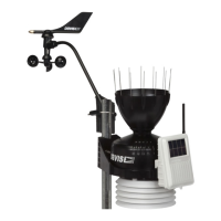
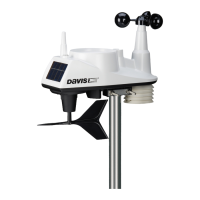
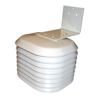
Guidance on positioning the sensor suite to avoid obstructions and ensure solar exposure for wireless models.

Configuring the ISS

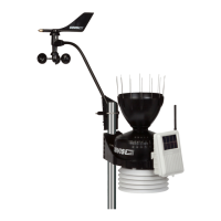
Instructions for setting up the ISS, noting wired systems require no configuration, while wireless systems need ID code matching.

Applying Power to the ISS

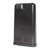
Details on powering the ISS via solar panel or cable, with recommendations for a backup battery for continuous operation.

Configuring the Wireless ISS

Setting the ID Code

Explains how to set matching ID codes between the ISS transmitter and receiver for communication, detailing dip switch settings.

Test Mode

Describes the function of Dip switch #4 for testing the LED indicator and the importance of turning it OFF to conserve power.

Specifications

FCC Part 15 Class B Registration Warning

Related product manuals