EasyManua.ls Logo

DAVIS Solar Radiation Sensor User Manual

DAVIS Solar Radiation Sensor
16 pages
To Next Page IconTo Next Page
Page #1 background imageLoading...
Page #1 background image
Product # 7821, 7823, 6450
S
OLAR
R
ADIATION
S
ENSOR
S
TANDARD
, I
NDUSTRIAL
, &
V
ANTAGE
P
RO
VERSIONS
The Davis Solar Radiation Sensor is a precision instrument that detects radia-
tion at wavelengths of 300 to 1100 nanometers. The spectral response of the sil-
icon photodiode detector is a good match to the spectrum of solar irradiance.
Avoid touching the small white diffuser at the top of the sensor.
Any skin oil
on this surface will degrade the sensitivity of the sensor. To remove any oil
present, clean the diffuser with a clean swab and ethyl (denatured) alcohol. Do
NOT use rubbing alcohol.
The sensor is made up of the following components:
Shield
The outer shell shields the sensor body from thermal radiation and pro-
vides a path for convection cooling of the body, minimizing heating of
the sensor interior. It provides a cutoff ring for cosine response, a level
indicator, and fins to aid in aligning the sensor with the sun’s rays.
Body
The body houses the following components:
Diffuser
Welded to the body for a weather-tight seal. Provides excellent
cosine response.
Detector
An hermetically-sealed silicon photodiode.
Amplifier
The amplifier converts the detector current into a 0 to +2.5V signal.
Cable
The standard version of the sensor includes an attached 40' (12 m)
standard cable. The industrial version includes a 16' (5 m) shielded
cable. The Vantage Pro version comes with a 3' (0.9 m) standard
cable.
Question and Answer IconNeed help?

Do you have a question about the DAVIS Solar Radiation Sensor and is the answer not in the manual?

DAVIS Solar Radiation Sensor Specifications

General IconGeneral
BrandDAVIS
ModelSolar Radiation Sensor
CategoryAccessories
LanguageEnglish

Summary

Solar Radiation Sensor Overview

Sensor Description and Components

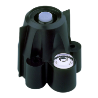
Details the sensor's function, spectral response, and its constituent parts like Shield, Body, Diffuser, Detector, Amplifier, and Cable.

Diffuser Cleaning Procedure

Specific instructions for cleaning the sensor's diffuser using ethyl alcohol, avoiding rubbing alcohol.

Installation Hardware and Tools

Mounting Hardware Components

Lists screws, springs, washers, retainers, and cable clamp required for sensor installation.

Required Tools and Materials

Lists necessary tools such as screwdrivers, drill bits, and wire cutters for installation.

Standard and Industrial Installation

Testing the Sensor

Steps to test the sensor by connecting to the SIM and verifying readings on the console.

Typical Standard Installation

Illustrates connecting the sensor cable to the SIM for standard installation setups.

Typical Industrial Installation

Illustrates connecting the sensor cable to the SIM for industrial installation setups.

Mounting Procedures

Mounting on Sensor Mounting Arm (SMA)

Step-by-step guide to attach the sensor to the SMA, including leveling and cable securing.

Mounting on Sensor Tilting Bracket

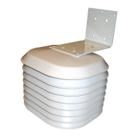
Instructions for mounting the sensor onto the tilting bracket for specific angles.

Mounting on a Wood Surface

Detailed steps for mounting the sensor directly onto a wood surface using a template.

Vantage Pro Version Installation

Mounting on Sensor Mounting Shelf

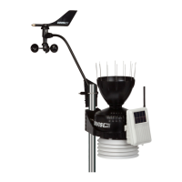
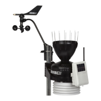
Guide to mount the sensor on the ISS shelf for Vantage Pro systems.

Testing and Cable Routing

Steps for testing the sensor and routing its cable on the Vantage Pro ISS.

Sensor Maintenance and Support

Maintaining the Sensor

Guidance on cleaning the diffuser and sensor recalibration recommendations.

Technical Support Information

Contact details and troubleshooting advice for sensor issues.

Related product manuals