0.37
4 1"
132
255
403 10
6 1¼” 204 441 12
12
1½”
178
267
514
22
DBH 2-40
0.75
1.5
DBH 4-50
DBH 8-30
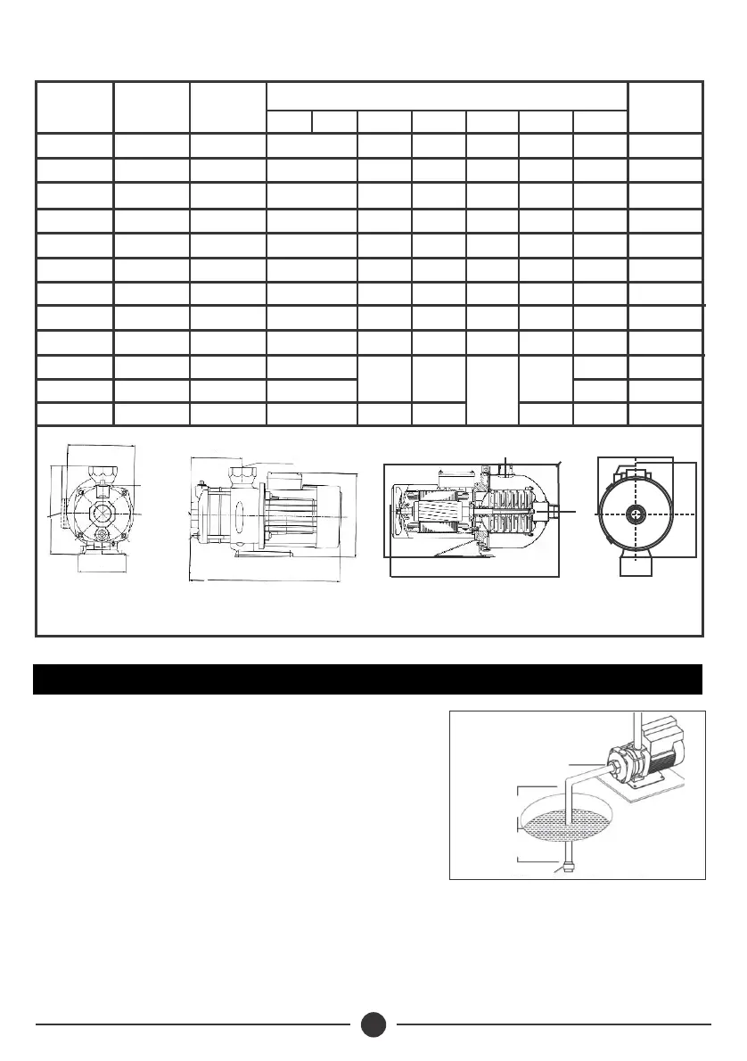
DB Cross Sectional Diagram
142
140
480
680
820
1020
1450
1710
1080
2700
1500
3
PUMP DATA
Model
Current
(A)
Dimensions(mm)
Weight
(kg)
DNA C H L1
B
Power
(W)
DNB
A
DB 2-30 2.3
12
DB 2-50
3.2
11
3.5
DB 4-30 12
4.3DB 4-40
13
DB 4-60 6.2
15
18
29
19
27
DB 8-30
3.4
5.1
DB 8-50
DB 12-30
4.8
6.8
DB 12-50
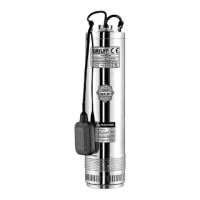
2) INSTALLATION
! Site in a dry, well ventilated and weather
proof location with an ambient
0
temperature of no more than 40 C.
! Locate on a solid flat surface ensuring the
shaft is in a horizontal position.
! Ensure that the diameter of the suction
pipe is at least the size of the pump
suction inlet. If the suction depth exceeds
4 meters then a one size larger diameter pipe. If the suction depth
exceeds 4 meters then a one size larger diameter pipe should be used,
though for maximum pump performance suction height should be
minimised.
Foot Valve
UPWARD SLOPE
TO SUCTION
Max 6m
Min 50cm
1"
1"
1¼”
1¼”
1¼”
1¼”
1½”
1½”
1¼”
119
155
137
164
218
138
108
138
108
130
130
130
130
130
130
130
130
130
141
141
141
141
141
181
181
181
181
228
228
228
228
228
248
248
248
248
327
363
344
372
465
420
390
450
390
B1
H
B
L1
DNB
A
DNA
H
DBH Cross Sectional Diagram
C
DNB
C
A
DNA
H
B
L1